Installation Guide
CONFIDENTIAL
TG-0057_19 TM4 SUMO HD CO300-A1_A2_A2.5 Installation Guide
© Dana TM4 inc., 2013-2020
Page 25 of 42
2020-11-20
4.5.5 Phase cables
Power cables are required between the MCU and the motor to connect each phase; cables of a pre-
determined length are attached to the MCU by TM4 and must then be connected to the motor by the
customer.
Carefully read all safety instructions related to electrical installation in Section 4.5.1 and general information
for installing cables and harnesses in Section 4.5.2 before continuing with your integration.
IMPORTANT NOTE
: Disable the high-voltage and auxiliary batteries before connecting or disconnecting
the phase cables.
4.5.5.1 Preparing or modifying the phase cable assembly
In the event that TM4 has not been requested to deliver prepared cables with the drive, it is the integrator's
responsibility to complete the cable preparation before installation. For detailed cable end preparation
information, see the cable end specification document for your installation [7].
Note
: Phase cables can be up to a length of 5 m.
4.5.5.2 Installing the phase cable assembly
Using the harness you have prepared or purchased from TM4, refer to the product interface drawing [11]
and cable harness specification [13] for illustrated installation information. See Figure 8 for the location of
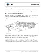
phase cable connectors on the MCU casing.
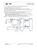
Figure 8
Phase cable gland locations
To provide greater flexibility when integrating the system into the vehicle and to prevent the cables from
touching or crossing over each other when connecting the motor to the MCU, we recommend two possible
phase cable configurations: standard and reversed. Both the TM4 MCU and motor have numbers/letters
engraved on the casing to help you with the installation. See Table 5 for both standard and reversed
mappings.
•
Standard
: Cables connected with logical letter/number sequence (A1-1; B1-2; etc.).
•
Reverse
: Cables connected with reverse letter/number sequence (A1-9; B1-8; etc.).


