Installation Guide
CONFIDENTIAL
TG-0057_19 TM4 SUMO HD CO300-A1_A2_A2.5 Installation Guide
© Dana TM4 inc., 2013-2020
Page 38 of 42
2020-11-20
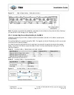
Figure 16
High-voltage battery – Cable gland location
Note
: The screws required for this installation procedure are not installed on the product at time of delivery;
you will find them in small bags in the shipping crate.
4.5.9 Connecting the auxiliary battery to the MCU
Carefully read all safety instructions related to electrical installation (Section 4.5.1) before connecting the
auxiliary battery.
The auxiliary battery is required to power the MCU. The negative terminal of the battery must be connected
to the frame of the vehicle (chassis).
To protect the system against short circuit, add a fuse in series with the positive terminal of the auxiliary
battery. See Table 13 for MCU current information; Table 14 for fuse specifications and Figure 17 for the
fuse block diagram.
Table 13
Auxiliary battery – Steady state and inrush currents
Specifications
Units
Values (12 V)
Values (24 V)
Maximum MCU steady state current
A
4.5
3
Maximum MCU inrush current
A
< 10
< 10
Maximum MCU quiescent current
mA
< 1
< 1.5
Note:
Typical values are given at 25
°
C.
Table 14
Auxiliary battery – Fuse specifications
Specifications
Units
Values
(12 V/24 V)
Current rating
A
10
Fuse type
-
Fast-acting
Figure 17
Auxiliary battery – Fuse block diagram

