Kollmorgen
SYSTEM WIRING
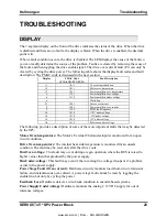
SERVO
STAR
®
SP3 Power Block
19
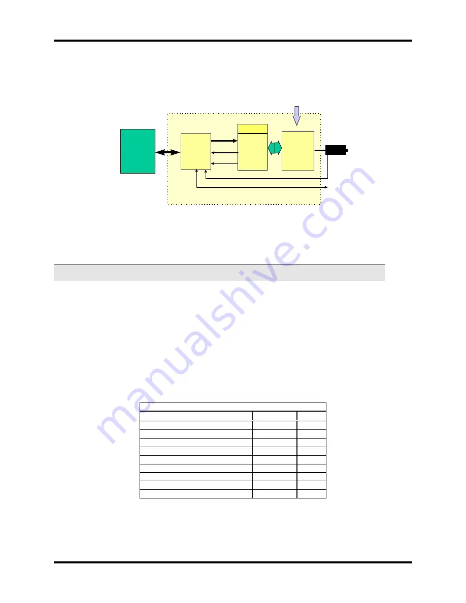
Integrated 8F Option Block Diagram
Pow er
Stage
C ontrol
B oard
PW M
I
D ata
Faults
Interface
B oard
8F
PM A C -2
M otor
E ncoder / H alls
Flags
O ne A xis
ServoStar PB
7-seg display
A C Supply
SYSTEM INTERCONNECT
The following sections provide connector information and the system connections up to the
motor power and feedback connections. Cabling purchased from Danaher Motion Kollmorgen
directly completes the system connections. Customers making their own cables can refer to
Appendix A for drive/motor pinout connections.
Connector C1: Hall Effect Device Feedback
Connector C1 interfaces between the SP3 and the Hall Effect Devices (HED) on the motor.
These signals may be used when the feedback consists of HEDs only. The HED connections are
repeated on connector C2, and only one should be used, since the signals are interconnected
within the drive. Connector C1 is a 9 pin D-sub male with the pin descriptions below.
Connector C1 Hall Effect Device Feedback
Function Symbol
Pin
HED-1 reference
H1-
1
HED-2 reference
H2-
2
HED-3 reference
H3-
3
No Connection
NC
4
No Connection
NC
5
HED-1 input
H1+
6
HED-2 input
H2+
7
HED-3 input
H3+
8
No Connection
NC
9
www.szcxi.com | From
:
KOLLMORGEN


