33
The list below describes the factory defaults for each of the inputs. A logic input is active
when current is flowing through the photo diode. Inactive inputs are open circuited.
Default Input Functions
DINP1
(ENABLE)
Input 1: This input enables the drive. When input 1 is activated (current
flowing in the photo diode), the drive is enabled. This input must be actively
driven to enable the drive. An open circuited input disables the drive.
DINP2
Input 2: General purpose input default assigned to Home Switch.
DINP3
Input 3: General purpose input default assigned to Start Move BCD.
DINP4
Input 4: General purpose input default assigned to Move Select Bit. One of
two inputs that can be assigned as end-travel limit switch inputs.
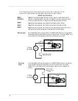
Sinking Logic
For compatibility with sinking outputs, the DINP COM terminal is connected to
the positive terminal of a power source (4.0 to 30 VDC). The input (DINP1-3) is
connected to the sinking logic output of the field device as shown.
External
4 - 30 VDC
Power Supply
Sinking Logic Output
from Field Device
J4-1
DINP COM
J4-2, 3, 4, 5
DINP1-3,
DC
+
-
4.32 k
4.64 k
DRIVE
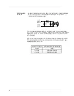
Sourcing
Logic
For compatibility with sourcing outputs, the DINP COM terminal is connected
to the negative terminal of the power source (4.0 to 30 VDC). The input
(DINP1-3) is connected to the sourcing logic output on the field device as
shown.
J4-1
DINP COM
J4-2, 3, 4, 5
Sourcing Logic
Output from Field
Device
External
4 - 30 VDC
Power Supply
DC
+
-
4.32 k
4.64 k
DINP1-3
DRIVE
Summary of Contents for S20630
Page 6: ......
Page 15: ...9 3 1 6 E 6 E 6 E 6 E 6 E 6 E 6 E 6 E...
Page 19: ...13 1 6 11 General 3H 3 3H 5 E 3 3 5J...
Page 94: ......

