48
3.2
P
ULSE
(S
TEP
)
AND
D
IRECTION
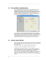
When using pulse and direction the pulses for command come in on the A
channel and the direction on the B channel. The data in Section 3.1 will
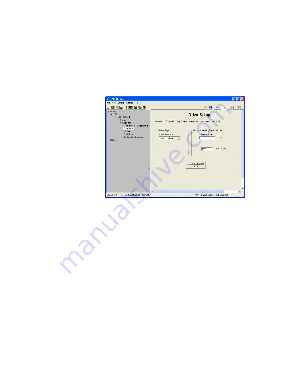
facilitate the electrical interface design. Select the ‘Mode of Operation (Drive
Setup Menu) to ‘Electronic Gearing. Set the ‘Command Mode’ (Gearing menu)
to ‘Pulse and Direction. And finally, set the pulses per revolution as the
‘Electronic Gearing Command Ration as revs / pulses. In the below diagram
the system is set up for 1600 pulses per motor revolution.
If no Digital Input is assigned to begin the gearing then the motor will follow
pulses a soon as the drive is enabled. A Digital Input can be assigned to start
the gearing With or Without correction. If one of these is selected then the input
is edge-triggered, meaning that it must go from off-to-on while the drive is
ready and enabled. (More on With and Without Correction in Section 3.3).
3.3
D
IGITAL
I
NPUT
N
OTES
Inputs selected for absolute or relative move must be turned on and maintained
on for the duration of the move. Motion will terminate if the input assertion goes
off during the move.
Only inputs 2 and 3 can be assigned as Registration Move Inputs.
Only Inputs 4 and 5 can be assigned as Direction Limit Inputs.
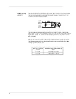
Using Input 5: Input 5 (DINP5 / HSINP) is an uncommitted high speed opto
isolator available at J4 pins 10 and 11. Simply tie pin 10 to the common rail
(Pin 1) if the common rail is tied to the positive supply an switch pin 11.
Reverse 10 and 11 if the common rail ties to the negative of the supply. Digital
input 5 is rated for 3 to 6 volt operation. If the application requires higher
voltage than simply make the tie to the I/O common rail with a series dropping
resistor.
Summary of Contents for S20630
Page 6: ......
Page 15: ...9 3 1 6 E 6 E 6 E 6 E 6 E 6 E 6 E 6 E...
Page 19: ...13 1 6 11 General 3H 3 3H 5 E 3 3 5J...
Page 94: ......


