background image

112

Standalone MMC Hardware Manual

Standalone Digital MMC Control

version  15.1

    Danaher  Motion

5.5.5

Digital Link Ports

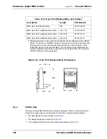
The four 8-pin RJ-45 Digital Link Port connectors (labeled “B1”, “B2”, “B3”, and “B4” 
on the front of the Control) provide communications between Control and Digital MMC 
Smart Drives. Also provided on the RJ-45 connector is a green “Link” light (which will 
be on if there is a Drive connected to the branch) and a green “Activity” light (which will 
be on whenever a data packet is transmitted to the drive(s) on the branch).

Each of the four branches (two branches on the Digital MMC-D32) can control up to 
16 drives. A “straight-through” shielded cable must be used when connecting the 
Control to the Digital Drive. Connect the cable from the Control to the Drives “IN” 
connector. Refer to the MMC Smart Drive manual for Drive information.

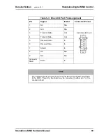
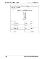
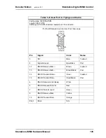
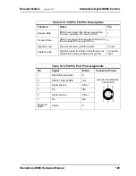
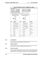
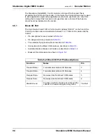
Pin descriptions for are provided in 

Table 5-19

Pin assignments are provided in 

Table 5-20

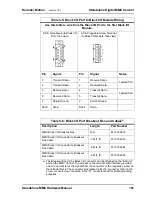
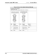
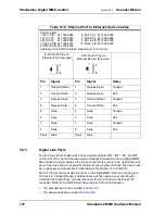
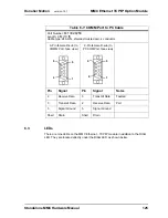
Table 5-18: Ethernet Port to Ethernet Device Cables

Part Numbers:
.3 M (1.0 ft):    M.1302.8285          .6 M (2.0 ft):   M.1302.8286
1 M (3.3 ft):     M.1302.8287           2 M (6.6 ft):   M.1302.8288
3 M (9.8 ft):     M.1302.8289           5 M (16.4 ft): M.1302.8300
10 M (32.8 ft): M.1302.8301         15 M (49.2 ft): M.1302.8302
30 M (98.4 ft): M.1302.8303
Cable type: 28 AWG, shielded, twisted pair, 8 conductor.

8-Pin RJ-45 Plug (to 

Ethernet Port, face view)

8-Pin RJ-45 Plug (to 

Ethernet Device, face view) 

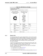
Pin

Signal

Pin

Signal

Notes

1

Transmit Data +

1

Receive Data +

Twisted

2

Transmit Data -

2

Receive Data -

Pair

3

Receive Data +

3

Transmit Data +

Twisted

6

Receive Data -

6

Transmit Data -

Pair

4

None

4

None

Twisted

5

None

5

None

Pair

7

None

7

None

Twisted

8

None

8

None

Pair

Shell

Drain

Shell

Drain

1

8

1

8

Summary of Contents for Standalone MMC

Page 1: ... Version 15 1 Keep all product manuals as a product component during the life span of the product Pass all product manuals to future users owners of the product Catalog No M 1300 7620 Part No M 3000 0451 Danaher Motion IND CONT EQ 89X2 ...

Page 2: ...nt may be made without notice Printed in USA All rights reserved No part of this work may be reproduced in any form by printing photocopying microfilm or any other method or processed copied or distributed by electronic means without the written permission of Danaher Motion Edition Valid for Description 03 2007 PiCPro V16 1 Added MMC S16 Sercos Plus Module ...

Page 3: ...ed including but not limited to implied warranties of merchantability and fitness for a particular purpose It is the responsibility of the product user to determine the suitability of this product for a specific application DO NOT ATTEMPT to use any Danaher Motion product until the use of such product is completely understood It is the responsibility of the user to make certain proper operation pr...

Page 4: ......

Page 5: ...trol 17 3 2 Adding an Option Module to the MMC Control 18 3 3 Dimensions and Mounting of MMC with Option Modules Attached 20 3 4 System Power and Environment Requirements 21 3 4 1 General Power and Environment Requirements 21 3 4 2 Control Cabinet Specifications 22 3 4 3 Power Distribution Diagram 22 3 4 4 Grounding the System 23 3 4 5 Controlling Heat Within the System 24 3 4 6 Handling an MMC 25...

Page 6: ...ls 77 4 6 2 2 Aux I O Port Fast Inputs 79 4 6 2 3 Aux I O Port DC Inputs 81 4 6 2 4 Aux I O Port Encoder Input 82 4 6 2 5 Aux I O Port Analog Input 83 4 7 SERCOS Motion Control Connections Operation 83 4 7 1 SERCOS Receive and Transmit Ports 83 4 7 2 Loader Port 85 4 8 Replacing the MMC Battery 87 4 9 Specifications 89 5 Standalone Digital MMC Control 95 5 1 Introduction 95 5 2 Features 95 5 3 Ove...

Page 7: ...pecifications 145 10 MMC 32In 32Out Option Module 149 10 1 Introduction 149 10 2 Connections Operation 150 10 2 1 DC Output Operation 154 10 2 2 DC Input Operation 157 10 3 Specifications 159 11 CE and EMC Guidelines 161 11 1 Background on EMC Electromagnetic Compatibility Compliance 161 11 2 Background on Low Voltage Compliance 161 11 3 RFI Emission and Immunity 161 11 4 Classes of EMC Operating ...

Page 8: ...8 Standalone MMC Hardware Manual Table of Contents version 15 1 Danaher Motion ...

Page 9: ... 2 Contents of This Manual This manual includes the following major topics Information to safely operate and maintain the equipment in a safe manner User responsibilities for product acceptance and storage Power and environmental information for general power control cabinet ground ing heat control and handling Procedures for mounting wiring and connecting the MMC Control The function location and...

Page 10: ...port Contact Contact your local Danaher Motion representative for Sales and order support Product technical training Warranty support Support service agreements Danaher Motion Technical Support can be reached In the United States telephone 800 558 4808 Outside the United States telephone 920 921 7100 E mail address glmotion support danahermotion com Web site www glcontrols com ...

Page 11: ... or are involved with this equipment in any way should become totally familiar with this information prior to operating 2 1 1 User Responsibility It is the responsibility of the user to ensure that the procedures set forth here are followed and should any major deviation or change in use from the original specifications be required appropriate procedures should be established for the continued saf...

Page 12: ... personal or plant safety It should be noted that the use of safety signs does not replace the need for appropriate accident prevention measures Always read and follow the instructions based upon the level of hazard or potential danger 2 3 Warning Labels Hazard warning When you see this safety sign on a system it gives a warning of a hazard or possibility of a hazard existing The type of warning i...

Page 13: ...y devices are installed and operative and all doors which carry warning labels are closed and locked Ensure that all personnel are clear of those areas indicated as potentially hazard ous Remove from the operating zone any materials tools or other objects that could cause injury to personnel or damage the system Make sure that the control system is in an operational condition Make certain that all...

Page 14: ...fall onto the control equip ment or its peripheral equipment Horseplay around the control system and its associated equipment is dangerous and should be prohibited Never operate the equipment outside specification limits Keep alert and observe indicator lights system messages and warnings that are displayed on the system Do not operate faulty or damaged equipment Make certain proper service and ma...

Page 15: ...ment or wiring On completion close and lock panel doors All covers on junction panels should be fastened closed before leaving any job Never operate any controls while others are performing maintenance on the sys tem Do not bypass a safety device Always use the proper tool for the job Replace the main supply fuses only when electrical power is OFF locked out 2 9 Safe Cleaning Practices Do not use ...

Page 16: ...mmediately after they occur Never attempt to clean a control system while it is operating Never use water to clean control equipment unless you are certain that the equip ment has been certified as sealed against water ingress Water is a very good conductor of electricity and the single largest cause of death by electrocution ...

Page 17: ...he unit to your cabinet using the mounting slots on the MMC as shown Note the Standalone MMC Digital Control requires a minimum of 1 2 in clearance on the left side for proper fan air movement The MMC unit must be mounted vertically The recommended size of mounting hardware is 10 bolts with 10 star washers to ensure proper ground connection as shown in Figure 3 1 below ...

Page 18: ...nual The standard Standalone MMC Control MMC A2 MMC A4 and MMC S8 accepts up to two MMC Option Modules The Standalone MMC Control Plus MMC A2 Plus and MMC A4 Plus as MMC 55 13 97 mm 1 00 25 4 mm 2 10 53 34 mm 9 59 243 59 mm 8 75 222 25 mm 218 5 54 mm 1 05 26 67 mm 55 Side Cover Screw Head 040 Thickness 080 Thickness NOTE Add the side cover and screw head thicknesses to the unit s dimensions for to...

Page 19: ...he module Lift the side cover off and set aside 3 Locate the 50 pin square post socket at the top of the MMC board Press one side of the 50 pin square post male connector into this socket ensuring that the pins are aligned and it is firmly seated 4 Pick up the option module Line up the socket on the option module with the male end of the connector extending from the MMC ensuring that the pins are ...

Page 20: ... 3 Dimensions and Mounting of MMC with Option Modules Attached After attaching option modules to the MMC module mount the unit to your cabinet using the mounting slots on the MMC and the option module The recommended size of mounting hardware is 10 bolts with 10 star washers to ensure proper ground connection Cover Side of Module Side Screw Top Screws Bottom Screws 24 COM ...

Page 21: ...rmally only non conductive pollution occurs You are not required to install the system rack MMC 1 00 25 4 mm 2 10 53 34 mm 8 75 222 25 mm 218 5 54 mm 1 05 26 27 mm 55 13 97 mm Module Side Cover Screw Head 040 Thickness 080 Thickness NOTE Add the side cover and screw head thickness es to the unit s dimensions for total width 1 69 42 93 mm 1 28 9 59 243 59 mm Option Module Option Module 55 13 97 mm ...

Page 22: ...inet housing the MMC should have a NEMA 12 rating or better A cabinet with this rating protects its con tents from dust and mechanical damage must be large enough to provide adequate air circulation for the MMC drives and other components Always allow for adequate air flow through the MMC vents must have a rigid vertical surface to mount the MMC on should be positioned to allow the cabinet door to...

Page 23: ...mended that the same main disconnect switch be used for the MMC system and for all devices in the application 3 4 4 Grounding the System The ground of the MMC power source must be connected directly to a Single Point Ground SPG tie block The tie block should be made of brass or copper bolted or brazed to the control cabinet If the tie block is bolted rather than brazed scrape away paint or grease ...

Page 24: ... MMC must be mounted vertically to take advantage of this design Normally no fans or air conditioners are needed However if the environment outside the control cabinet is hot or humid you may need to use a fan heat exchanger dehumidifier or air conditioner to provide the correct operating environment CAUTION The Single Point Ground should be the only common point for all the ground lines If not gr...

Page 25: ...ul effects System heat is generated from power dissipated by field side input output components other components within the MMC 3 4 6 Handling an MMC The case protects the MMC s internal circuitry against mechanical damage in shipping and handling However like any electronics device the circuitry can be destroyed by temperatures over 55 C 131 F moisture condensing inside the module static discharg...

Page 26: ...s such as motor armature cables Maintain at least one inch of separation around signals Figure 3 5 below illustrates the recommended connections when using EMC compliant products Note that a capacitor is connected to the 24 VDC supply To prevent excessive conducted emissions from a DC power source typically 24 V used for digital I O a 1000 picofarad capacitor should be used Connect the capacitor f...

Page 27: ...ces but there will be self recovery when the noise subsides Do not operate transmitters arc welding equipment or other high noise radiators within one meter of an enclosure that has the door open Continue to equip inductive devices if they are in series with a mechanical contact or switch with arc suppression circuits These devices include contactors solenoids and motors Shield all cables that car...

Page 28: ... detected 3 6 Starting an Application To start an application 1 Turn off the main disconnect switch in the control cabinet If some devices are not powered from the control cabinet turn them off also 2 Connect the connectors according to your diagrams 3 Turn on power to the system The MMC goes through the following sequence The Power light labeled P goes on and stays on The Diagnostic light labeled...

Page 29: ...order to Turn off the entire application Turn off main disconnect which should also turn off all external power supplies to the appli cation unplug the DC power to the MMC Wire the I O to the application Turn off main disconnect which should also turn off all external power supplies to the appli cation unplug the DC power to the MMC Change the battery Turn off main disconnect which should also tur...

Page 30: ...ght comes on briefly while its diagnostic tests are running After the power up diagnostics run the Diagnostic light will be in one of the following states off indicating that the MMC is operating correctly on indicating that the power up diagnostics found a hardware problem with the MMC 3 8 5 Run time Diagnostic Status When the application is running the Scan light is on the Control constantly mon...

Page 31: ...nt memory There is insufficient memory on the CPU to run the cur rent program 222 Driver error No driver support on the CPU for the Option module Up date your system EPROMs 22_ Master rack error An Option Module in the master rack or the Motion Con trol Board in a Standalone MMC Control do not match what was declared in the hardware master declaration ta ble The number of flashes in the third digi...

Page 32: ...32 Standalone MMC Hardware Manual Installation Operation Maintenance version 15 1 Danaher Motion ...

Page 33: ...e Eight and 16 axis SERCOS versions available UL Listed and CE Marked 4 3 Overview The MMC Control consists of a Machine Control board and a Motion Control board contained within a metal enclosure External connections for the boards are located on the face of the enclosure The MMC Control offers a complete solution to both machine and motion control in a standalone unit The Standalone MMC family i...

Page 34: ...MMC Expansion Modules may be added to the MMC A2 Plus MMC A 4 Plus MMC S 8 Plus and MMC S16 Plus The following is a list of available MMC Option Modules MMC Ethernet Option Module see section 6 on page 119 MMC DeviceNet Option Module see section 7 on page 131 MMC Profibus Option Module see section 8 on page 137 MMC Axis I O Option Module limitations apply see section 9 on page 143 MMC 32 In 32 Out...

Page 35: ...Axis 1 Port Auxiliary LEDs I O Port Analog Motion MMC A4 Servo Control MMC S8 SERCOS Control MMC S16 also available Port Port Connection PicPro Block I O User General I O Power LEDs Control Side Port Port Port Connection Port RECV1 XMIT1 LOADER Machine Control Side Common to all MMC Controls SERCOS Motion Control Side Machine Control Side Common to all MMC Controls General I O Port MMC A2 also ava...

Page 36: ...ft side of the control The motion control side of the MMC unit can be either an Analog Servo board or a SERCOS board 4 3 2 1 Analog Servo board The Analog Servo board provides conventional analog digital interfacing for two or four drives The typical signals needed to interface to an analog drive are provided by the analog servo module The drive command is in the form of an analog voltage 10V Feed...

Page 37: ...eeded Table 4 2 below shows the distribution of the 24 Vdc power within the MMC system In most cases one power supply can be used for the entire control system However depending upon the modules drives and external I O used in your application you may split the power distribution into two or more power supplies For example the Axis I O on an MMC A2 module can be powered from the MMC from the drive...

Page 38: ...xternal device failure circuit breakers or fuses should be used in series with the 24 Vdc going to and coming from the MMC Specifi cally the circuit breakers or fuses should be sized for 10 A total on the 24 Vdc line coming into the MMC 1 A total from the 24 Vdc OUT pins of the AXIS and AUXILIARY I O connectors and 5 A total from the I O 24V pins of the GENERAL I O connector For maximum protection...

Page 39: ...ponent Lines 7 12 are for General I O Port Lines 14 21 are for Axis I O Ports Max Current mA Actual Current mA Number of I O Col A Subtotal mA Col B Current mA 7 General Inputs 7 5 7 5 8 General Outputs 250 9 250 10 250 11 250 12 250 13 Subtotal Power Bus 2 Add Column A Lines 7 12 5000 mA max 14 Axis inputs 7 5 7 5 15 Axis outputs 100 16 100 17 100 18 100 19 Auxiliary inputs 7 5 7 5 20 Fast inputs...

Page 40: ...O Port Lines 14 21 are for Axis I O Ports Max Current mA Actual Current mA Number of I O Col A Subtotal mA Col B Current mA 7 General Inputs 7 5 7 5 16 120 8 General Outputs 250 200 5 1000 9 250 100 9 900 10 250 11 250 12 250 13 Subtotal Power Bus 2 Add Column A Lines 7 12 5000 mA max 2020 14 Axis inputs 7 5 7 5 4 30 15 Axis outputs 100 50 8 200 16 100 100 17 100 60 18 100 19 Auxiliary inputs 7 5 ...

Page 41: ...ansion capability The MMC has a flash chip on board that allows you to load an application program into it This is standard on the MMC Having the application in the standard flash chip ensures that you will not lose the application if the battery fails On power up the application is transferred from the flash chip to RAM as it is when directly downloaded from PiCPro To place the application in fla...

Page 42: ...s the return path for signals 5 Data Terminal Ready Always high tied to 12V through 1K resistor 4 Request to send Always high tied to 12V through 1K resistor 7 Shield Ground Provides a path for shield current through the chassis to an external single point ground Connector Shell Table 4 6 PiCPro Port Pin Assignments Pin Signal In Out Connector Pinout 1 NC N A 9 pin male D sub 2 RS232 Receive Data ...

Page 43: ...e is described in Table 4 10 Connections to the Block I O Module are described in Table 4 11 Available Breakout Boxes and Cables are described in Table 4 12 Breakout Box dimensions are shown in Figure 4 2 Table 4 7 PiCPr0 Port to PC Cable Part Number M 1302 8250 Length 4 M 13 ft Cable type 24 AWG shielded twisted pair 4 conductor 9 Pin female D sub to PiCPro Port face view 9 Pin female D sub to PC...

Page 44: ...Modules 6 Shield Ground Provides a path for shield current through the chassis to an external single point ground 7 Shell Table 4 9 Block I O Port Pin Assignment Pin Signal In Out Connector Pinout 1 NC N A 9 pin female D sub 2 N C N A 3 Transmit Data Out 4 Transmit Data Out 5 Receive Data In 6 Receive Data In 7 Shield In 8 NC N A 9 NC N A Connector Shell Drain In NOTE Pin 7 of the Block I O port c...

Page 45: ... Number M 1016 2568 Length 3 M 10 ft Cable type 24 AWG twisted pair individually shielded 4 conductor 9 Pin male D sub to Block I O Port face view Pin Signal Color Notes 3 Transmit Data White Twisted 4 Transmit Data Black Pair 7 Shield N A with Shield 5 Receive Data Red Twisted 6 Receive Data Black Pair 7 Shield N A with Shield 1 9 5 6 ...

Page 46: ...ll Drain Table 4 12 Block I O Port Breakout Box and Cablesa a The Breakout Box for the Block I O connector can be attached to the BLK I O port on the MMC Control The pinouts on the terminal strip interface provide a one to one transfer of the signals from the connector to the respective pin s on the ter minal block The connector pins marked with the ground symbol on the screw connector are connect...

Page 47: ...communication between a serial device and the Control Pin descriptions are provided in Table 4 13 Pin assignments are provided in Table 4 14 The available Flying Lead cable is described in Table 4 15 The available RS 232 Exter HMI cable is described in Table 4 16 The available RS 485 Exter HMI cable is described in Table 4 17 Available Breakout Boxes and Cables are described in Table 4 18 Breakout...

Page 48: ... the Control that it can transmit data to the connected serial device 7 RS 232 Data terminal ready This output from the Control is always high 12 Vdc 4 RS 485 Receive Data RS485 level signal that receives serial data from the connected serial device s 12 RS 485 Receive Data RS485 level signal that receives serial data from the connected serial device s 13 RS 485 Transmit Data RS485 level signal th...

Page 49: ... 15 pin HD male D sub 2 N C N A 3 N C N A 4 RS232 Data terminal ready 12 Vdc Out 5 RS232 Request to Send Out 6 N C N A 7 RS232 Clear to Send In 8 Signal Ground In Out 9 RS232 Receive Data In 10 RS232 Transmit Data Out 11 N C N A 12 RS485 Receive Data In 13 RS485 Receive Data In 14 RS485 Transmit Data Out 15 RS485 Transmit Data Out Connector Shell Drain In 5 1 15 11 ...

Page 50: ...male D sub to User Port face view Pin Signal Color Notes 3 N C Blue Twisted 8 Signal Ground Blue Black Pair 12 RS485 Receive Data Brown Twisted 13 RS485 Receive Data Brown Black Pair 14 RS485 Transmit Data Violet Twisted 15 RS485 Transmit Data Violet Black Pair 4 RS232 Data terminal Ready White 5 RS232 Request to send Red 7 RS232 Clear to send Green 9 RS232 Receive Data Yellow 10 RS232 Transmit Da...

Page 51: ...2 8453 Length 4 M 13 ft Cable type 24 AWG shielded twisted pair 4 conductor 15 Pin HD female D sub to User Port face view 9 Pin female D sub to Exter HMI COM2 Port face view Pin Signal Pin Signal Notes 9 Receive Data 3 Transmit Data Twisted 10 Transmit Data 2 Receive Data Pair 8 Signal Ground 5 Signal Ground Shell Drain Shell Drain 5 1 15 11 6 5 9 1 ...

Page 52: ...Shell Drain Shell Drain Table 4 18 User Port Breakout Box and Cablesa a The Breakout Box for the User Port connector can be attached to the USER PORT connector on the MMC Control The pinouts on the terminal strip interface provide a one to one transfer of the signals from the connector to the respective pin s on the terminal block The connector pins marked with the ground symbol on the screw conne...

Page 53: ...O devices and the Control This port provides 16 source only outputs described in detail in section 4 5 4 1 on page 57 and 16 sink or source inputs described in detail in section 4 5 4 2 on page 60 Pin descriptions are provided in Table 4 19 Pin assignments are provided in Table 4 20 The available Flying Lead cable is described in Table 4 21 Available Breakout Boxes and Cables are described in Tabl...

Page 54: ...rce 9 16 37 44 Sink Source select pin for DC Inputs 9 16 To make DC Inputs 9 16 sourcing inputs 24 Vdc applied to the DC Input turns the input on connect 24 Vdc Common to this pin To make DC Inputs 9 16 sinking inputs 24 Vdc Common applied to the DC Input turns the in put on connect 24 Vdc nominal to this pin 35 24 Vdc Out 24 Vdc power nominal is routed from the 3 pin Power connector to these pins...

Page 55: ...8 DCOUT8 Out 9 DCOUT9 Out 10 DCOUT10 Out 11 DCOUT11 Out 12 DCOUT12 Out 13 DCOUT13 Out 14 DCOUT14 Out 15 DCOUT15 Out 16 DCOUT16 Out 17 19 N C N A Pin Signal In Out 20 IO24V Out 34 IO24V Out 21 DCSS1 In 35 DCSS2 In 22 IO24C Out 36 IO24C Out 23 DCIN1 In 37 DCIN9 In 24 DCIN2 In 38 DCIN10 In 25 DCIN3 In 39 DCIN11 In 26 DCIN4 In 40 DCIN12 In 27 DCIN5 In 41 DCIN13 In 28 DCIN6 In 42 DCIN14 In 29 DCIN7 In ...

Page 56: ...reen Pair 26 DCIN4 White Pair 7 DCOUT7 Black Twisted 28 DCIN6 Green Twisted 8 DCOUT8 Blue Pair 29 DCIN7 Blue Pair 9 DCOUT9 Black Twisted 31 None Green Twisted 10 DCOUT1 Yellow Pair 32 None Yellow Pair 11 DCOUT1 Black Twisted 33 None Green Twisted 12 DCOUT1 Brown Pair 34 IO24V Brown Pair 13 DCOUT1 Black Twisted 35 DCSS2 Green Twisted 14 DCOUT1 Orange Pair 36 IO24C Orange Pair 15 DCOUT1 Red Twisted ...

Page 57: ...in controls the outputs In addition each output is protected with internal Table 4 22 General I O Port Breakout Box and Cables a a The Breakout Box for the General I O connector can be attached to the GEN I O port on the MMC Control and on the GEN I O A and GEN I O B ports on the MMC 32 In 32 Out Expansion module The pinouts on the terminal strip interface provide a one to one transfer of the sign...

Page 58: ...amping diodes Without clamping high voltage transients kickback from inductive loads might damage the module For safety reasons all outputs turn off no current flow when a scan loss condition occurs For more information on DC output operation refer to Section A 3 on page 174 of Appendix A ...

Page 59: ...trol Figure 4 5 General I O Outputs Connected to Loads 1 To MMC GENERAL CONNECTOR DC OUTPUT PINS Power Connector DC Power Supply _ SPG Common DCOUT1 DCOUT2 DCOUT3 DCOUT4 DCOUT5 DCOUT6 DCOUT7 DCOUT8 DCOUT9 DCOUT10 DCOUT11 DCOUT12 DCOUT13 DCOUT14 DCOUT15 DCOUT16 LOAD 3 5 7 9 11 13 15 ...

Page 60: ...CSS1 for Group A DCSS2 for Group B to IO24C for a sourcing configuration Connect the DCSS pin DCSS1 for Group A DCSS2 for Group B to 24 Vdc for a sinking configuration An example of connecting input devices in both a sink and source configuration is shown in Figure 4 6 In addition the first input of each Group Input 1 of Group A and input 9 of Group B can be programmed to provide a processor inter...

Page 61: ...Inputs Connected to Devices 23 MMC GENERAL CONNECTOR DC OUTPUT PINS DCIN1 DCIN2 DCIN3 DCIN4 DCIN6 DCIN7 DCIN8 25 27 29 I O 24V DCSS1 21 SINK 37 DCIN9 DCIN10 DCIN11 DCIN12 DCIN14 DCIN15 DCIN16 39 41 43 I O 24C DCSS2 SOURCE DCIN5 DCIN13 35 To Power Connector DC Power Supply _ SPG SWITCHING DEVICE 24 Vdc Common ...

Page 62: ...d side of the system Such supplies are not routed through the MMC but they should all have the same power cut off switch as the Control The 24 VDC applied at the MMC input power connector is also available To power the DC outputs To power the sink source inputs To power the axes interface To power any attached MMC Option Modules Figure 4 7 Pin Out for the 3 pin Power Supply Screw Terminal Connecti...

Page 63: ...eakout Box dimensions are shown in Figure 4 8 Table 4 23 Axis I O Port Pin Descriptions Function Notes Pin Encoder Input A A B B I I Provides connections to an incremental en coder having differential outputs 1 5 10 D A Output DA DA 10V D A output for controlling an analog drive having a differential input 8 9 DC Input DCIN DCIN Provides connection to an input device sink or source 6 7 DC Outputs ...

Page 64: ...ble 4 24 Axis I O Port Pin Assignments Pin Signal In Out Connector Pinout 1 A In 15 pin HD female D sub 2 A In 3 B In 4 B In 5 I In 6 DCIN In 7 DCIN Out 8 D A Out 9 DA Out 10 I In 11 24 Vdc Out 12 COM In 13 DCOUT1 In Out 14 DCOUT2 In Out 15 DCOSS In Out Connector Shell Drain In 5 1 15 11 ...

Page 65: ... ft M 1302 5993 Cable type 28 AWG shielded twisted pair 18 conductor 15 Pin HD male D sub to Axis I O Port face view 26 Pin HD male D sub to MMC Smart Drive I O Port face view Pin Signal Pin Signal Notes 1 A 1 A Twisted 2 A 2 A Pair 3 B 3 B Twisted 4 B 4 B Pair 5 I 5 I Twisted 10 I 6 I Pair 11 24 Vdc 10 IO24V Twisted Pair 12 COM 16 IOCOM 20 AWG 13 DCOUT1 17 IN1 Twisted 14 DCOUT2 18 IN2 Pair 6 DCIN...

Page 66: ...le D sub to Axis I O Port face view Pin Signal Color Notes 1 A Blue Twisted 2 A White Blue Pair 3 B Black Twisted 4 B White Black Pair 5 I Red Twisted 10 I White Red Pair 8 D A Green Twisted 9 D A White Green Pair 6 DCIN Yellow Twisted 7 DCIN White Yellow Pair 11 24 Vdc Orange Twisted 11 24 Vdc White Orange Pair 12 COM Brown Twisted 13 DCOUT1 White Brown Pair 14 DCOUT2 Violet Twisted 15 DCOSS Whit...

Page 67: ... more information on DC output operation refer to Section A 3 on page 174 of Appendix A Table 4 27 Axis I O Port Breakout Box and Cables a a The Breakout Box for the Axis Connector can be attached to the A1 A2 A3 and A4 ports on the Standalone MMC Control or the MMC Axis I O Option Module The pinouts on the terminal strip interface provide a one to one transfer of the signals from the connector to...

Page 68: ... Standalone MMC Control version 15 1 Danaher Motion Figure 4 9 Axis I O DC Output Source Configuration DC OUT 1 DCOSS DC OUT 2 24V COM 13 15 14 11 12 Drive Enable Drive Reset Sourcing Outputs Sinking Inputs MMC Axis I O Connector Drive ...

Page 69: ...he drive enable and drive reset inputs When an output is turned on current can flow through the switch in either direction This allows the outputs to be connected in a sink or source configuration One of the input pins should be connected to either 24 Vdc or COM The remaining input pin should be tied to the input signal that will be switching Refer to Figure 4 11 For safety reasons all outputs tur...

Page 70: ...nalog output section a 16 bit digital word to each analog output channel Each digital word is converted to a corresponding voltage within the range of 10 Vdc The voltage is buffered and brought out to a pair of I O connections as a differential type voltage output This output is less subject to interference from electrical noise than a single ended output would be You can adjust each analog output...

Page 71: ...s The encoder signals should be quadrature type All encoder wiring between the MMC and the drive should be shielded twisted pair as shown in Figure 4 13 For more information on the Encoder input operation refer to Section A 4 on page 175 of Appendix A NOTE The power supply that powers the encoder must be referenced to the power supply that powers the MMC This is done by connecting the common ter m...

Page 72: ...DC inputs described in detail in section 4 6 2 3 on page 81 One quadrature incremental encoder channel described in detail in section 4 6 2 4 on page 82 One 12 bit resolution analog input channel described in detail in section 4 6 2 5 on page 83 Additional information is provided in this section as follows Pin descriptions fare provided in Table 4 28 Pin assignments are provided in Table 4 29 The ...

Page 73: ...uts 1 6 are sourcing 31 DC Sink Source B DCSSB If this pin is connected to 24 Vdc inputs DCIN1 DCIN6 are sinking If this pin is con nected to 24 Common inputs DCIN7 DCIN12 are sourcing 38 Analog Input ANL GIN ANLGIN 10V 16 bit A D input 13 14 Fast Inputs 1 5 FASTIN1 5 FASTIN1 5 Differential Fast Inputs for latching Encoder position 16 17 19 20 22 23 25 26 28 29 24 Vdc out 24 Vdc output to be used ...

Page 74: ... 29 FASTIN5 In 6 I In 30 Shield In 7 Shield In 31 DCSSA In Out 8 9 24 Vdc Out Out 32 DCIN1 In 10 11 COM In 33 DCIN2 In 12 5 Vdc Out Out 34 DCIN3 In 13 ANLGIN In 35 DCIN4 In 14 ANLGIN In 36 DCIN5 In 15 Shield In 37 DCIN6 In 16 FASTIN1 In 38 DCSSB a In Out 17 FASTIN1 In 39 DCIN7a In 18 Shield In 40 DCIN8a In 19 FASTIN2 In 41 DCIN9a In 20 FASTIN2 42 DCIN10 a In 21 Shield 43 DCIN11a In 22 FASTIN3 a a ...

Page 75: ... FASTIN4 a White Pair 7 Shield Black Twisted 28 FASTIN5 Green Twisted 8 24 Vdc Blue Pair 29 FASTIN5 Blue Pair 9 24 Vdc Black Twisted 31 DCSSA Green Twisted 10 COM Yellow Pair 32 DCIN1 Yellow Pair 11 COM Black Twisted 33 DCIN2 Green Twisted 12 5 Vdc Out Brown Pair 34 DCIN3 Brown Pair 13 ANLGIN Black Twisted 35 DCIN4 Green Twisted 14 ANLGIN Orange Pair 36 DCIN5 Orange Pair 15 Shield Red Twisted 37 D...

Page 76: ...nector to the respective pin s on the terminal block The connector pins marked with the ground symbol on the screw con nector are connected to the D connector shell for shield grounding purposes Description Length Part Number MMC Aux I O Breakout Box b b Aux I O Breakout Box dimensions are shown in Figure 4 14 N A M 1016 2531 MMC Aux I O Breakout Box with Encoder Isolation c c See section 4 6 2 1 ...

Page 77: ...kout Box uses 5 Vdc from pin 12 of the Control to power it s internal circuitry there is no 5 Vdc current to power the encoder Therefore the pin 12 screw terminal on the Isolated Breakout Box does not carry 5 Vdc and the encoder must be powered by an external supply When using the Isolated Breakout Box the index inputs I I must be con nected If the connected encoder does not provide the index func...

Page 78: ...ential Input Voltage Range 2 5 volts to 7 0 volts Differential Input Current Range 2 5 ma Input Voltage 2 5 volts to 30ma Input Voltage 7 0 volts Input pulse width minimum 600 nanoseconds Input frequency maximum on A or B inputs from Quadrature output encoder 250KHz 1 0 MHz count rate using quadrature edges Input frequency maximum on A or B inputs from Pulse output encoder 500KHz 500KHz count rate...

Page 79: ... connected in either a source or sink configuration The source configuration is illustrated in Figure 4 17 and the sink configuration is illustrated in Figure 4 18 IMPORTANT When using the Isolated Breakout Box the index inputs I I must be con nected If the connected encoder does not provide the index function con nect I on the Breakout Box to 5 Vdc and I to 5 Vdc Common Failure to connect I and I...

Page 80: ...t Inputs Connected Using Shielded Twisted Pair Source Figure 4 18 Fast Inputs Connected Using Shielded Twisted Pair Sink FI 1 24V MMC AUX I O Connector 16 17 FI 1 Source Switch Shield CHS 18 Shielded Twisted Pair FI 1 24V MMC AUX I O Connector 16 17 FI 1 Sink Switch Shield CHS 18 Shielded Twisted Pair ...

Page 81: ...g configuration by connecting the DCSS pin to either the 24 Vdc pin on the Aux I O Port or to the 24 Vdc of an external supply Both sinking and sourcing configurations using the Aux I O 24V and COM pins are shown in Figure 4 19 All 12 inputs are available on the four axis MMC A4 and 6 inputs are available on the two axis MMM A2 For more information on DC input operation refer to Section A 2 on pag...

Page 82: ...uadrature type All encoder wiring between the MMC and the drive should be shielded twisted pair as shown in Figure 4 20 For more information on the Encoder input operation refer to Section A 4 on page 175 of Appendix A Figure 4 20 Aux Port MMC Encoder Input NOTE The power supply that powers the encoder must be referenced to the power supply that powers the MMC This is done by connecting the common...

Page 83: ...tional ring port located at the top of the module Each ring port has a receive and a transmit fiber optic connector There is also an RS232 port used for loading FLASH memory updates The SERCOS board is controlled by an application created in PiCPro An on board processor interprets the functions and performs appropriate operations according to the SERCOS communications protocol Data Transfer Rates ...

Page 84: ...0m 6mm AA 1 M 3 3 ft M 1302 6400 SERCOS 2 00m 6mm AA 2 M 6 6 ft M 1302 6401 SERCOS 3 00m 6mm AA 3 M 9 8 ft M 1302 6402 SERCOS 5 00m 6mm AA 5 M 16 4 ft M 1302 6403 SERCOS 10 00m 6mm AA 10 M 32 8 ft M 1302 6404 SERCOS 15 00m 6mm AA 15 M 49 2 ft M 1302 6405 SERCOS 30 00m 6mm AA 30 M 98 4 ft M 1302 6406 a SERCOS Cables can be used to make the connection between a Standalone MMC SERCOS Control and a SE...

Page 85: ...on the Module Pin descriptions for are provided in Table 4 34 Pin assignments are provided in Table 4 35 The available SERCOS Loader Port to PC cable is described in Table 4 36 MMC MMC SERCOS Module Up to eight SERCOS slaves SERCOS Slave 1 SERCOS Slave 2 SERCOS Slave n Fiber Optic Ring Feedback and Diagnostics Position Velocity or Torque Commands PC connected to RS232 port for Field Updates of R T...

Page 86: ...ansmits serial data to the connected PC running PiCPro 3 Signal Ground Provides the return path for signals 5 Shield Ground Provides a path for shield current through the chassis to an external single point ground Connector Shell Table 4 35 SERCOS Loader Port Pin Assignments Pin Signal In Out Connector Pinout 1 NC N A 9 pin male D sub 2 RS232 Receive Data In 3 RS232 Transmit Data Out 4 NC N A 5 Si...

Page 87: ...e standard precautions before handling any electronics component 4 Lay the MMC system on the work surface If there are no optional modules attached remove the cover by removing the five screws two on top two on the bottom and one on the right side of the MMC If there are one or more optional modules attached remove the four screws that attach the first optional module and remove the MMC from the o...

Page 88: ...o gently pry up the battery clip Slide the battery out Replace it with a 3V coin cell BR2032 battery side up 7 Screw the cover or optional modules back on Return the MMC to the cabinet Connect the power cable Turn on power and check the lights WARNING DO NOT touch any of the capacitors Do not touch the pins on any of the ICs Even with precautions against static you may destroy the circuitry Batter...

Page 89: ...2 7096 X3 256K 128K 64K 20 20 16 8 3 1 MMC S8 Plus M 1302 7479 X3 256K 128K 64k 8 8 8 4 MMC S16 Plus M 3000 0472 X3 256K 128K 64K 8 8 8 6 Table 4 38 General Specifications CPU 32 bit RISC processor with numeric coprocessor Battery 3V Coin Cell BR2032 lithium battery CAUTION for Lithium Batteries Danger of explosion if battery is incorrectly replaced Replace only with the same or equivalent type re...

Page 90: ...e ments for programmable controllers Operates with emissions below EN55011 CISPR 11 Class A limits Immune to Electrostatic discharge 4K V contact mode 8K V air discharge per EN61000 4 2 RF electromagnetic fields per EN61000 4 3 ENV 50141 and ENV50204 Electrical fast transients per EN61000 4 4 Magnetic fields per EN61000 4 8 Refer to the EMC Guidelines for more information UL and C UL Listed E12641...

Page 91: ...rt Encoder Input Input channels 3 or 5 Input receiver 26C32 differential RS422 receiver Recommended Encoder Drivers 7272 75183 8830 75114 9614 26LS31 or equivalent Encoder signals Differential quadrature Input threshold 750 mV Input termination 120 ohm provided on board Maximum input voltage 5 V Maximum A or B input frequency 250 K Hz 1 M feedback unit count rate Fast input voltage Nominal 24 VDC ...

Page 92: ...uaranteed off voltage 5 VDC Turn on off time 1 ms Fast inputs 50 μsec Gen I O Port DC Outputs Number of outputs 16 outputs Input voltage Nominal 24 VDC 30 VDC maximum Configuration Two groups of eight solid state switches Protection of logic circuits Optical isolation between the logic and field side transient suppression on the 24V external supply Maximum current 25 A per output Voltage range 24 ...

Page 93: ...MMC S8 or two rings MMC S16 with from one to eight Sercos drives per ring SERCOS port SMA female connectors for interfacing to 1000 µ meter plas tic fiber optic cable with SMA male connectors Fiber optic receiver specifications Peak input power optical level low 31 2dBm max Peak input power optical level high 20 0 dBm min 0 0dBm max Fiber optic transmitter specifications Peak output power optical ...

Page 94: ...94 Standalone MMC Hardware Manual Standalone MMC Control version 15 1 Danaher Motion ...

Page 95: ...RAM Block I O port for I O expansion Up to 4 MMC Option Modules can be user installed 32 and 64 axis versions available PicPro USB high speed peripheral port future User USB high speed peripheral port future Compact Flash memory socket future UL Listed and CE Marked 5 3 Overview The Standalone Digital MMC D64 Control can control up to 64 Digital MMC Smart Drives 32 drives on the D32 providing 64 3...

Page 96: ...so MMC Option Modules attached to the Standalone Digital MMC Control draw power from the Control s 24 Vdc connector When determining the size of the 24 Vdc power supply use the worksheet found in Table 5 1 Lights S P D Ethernet Port ENET Digital Link Port Branch 1 B1 Digital Link Port Branch 2 B2 Digital Link Port Branch 3 B3 Digital Link Port Branch 4 B4 Future USER USB Future PiCPRO USB Power Co...

Page 97: ...ied Performs diagnostic tests Checks the battery Performs routine maintenance tasks Executes the application program Communicates with any attached MMC Option Modules Communicates with any Block I O connected to the Block I O port Communicates with workstation connected to the PiCPro port Communicates with any serial device s connected to the User Port Communicates with any device s connected to t...

Page 98: ... serial communication between 1 to 77 Block I O modules and the Control Pin descriptions for are provided in Table 5 2 Pin assignments are provided in Table 5 3 The available Flying Lead cable is described in Table 5 4 Connections to the Block I O Module are described in Table 5 5 Available Breakout Boxes and Cables are described in Table 5 6 Breakout Box dimensions are shown in Figure 5 2 Table 5...

Page 99: ...tor Pinout 1 NC N A 9 pin female D sub 2 N C N A 3 Transmit Data Out 4 Transmit Data Out 5 Receive Data In 6 Receive Data In 7 Shield In 8 NC N A 9 NC N A Connector Shell Drain In NOTE Pin 7 of the Block I O port connector is connected to the connector shell with in the MMC Therefore the shield may be connected to either pin 7 or the connector shell 6 5 9 1 ...

Page 100: ...Part Number M 1016 2568 Length 3 M 10 ft Cable type 24 AWG twisted pair individually shielded 4 conductor 9 Pin male D sub to Block I O Port face view Pin Signal Color Notes 3 Transmit Data White Twisted 4 Transmit Data Black Pair 7 Shield N A with Shield 5 Receive Data Red Twisted 6 Receive Data Black Pair 7 Shield N A with Shield 1 9 5 6 ...

Page 101: ...n Shell Drain Table 5 6 Block I O Port Breakout Box and Cablesa a The Breakout Box for the Block I O connector can be attached to the BLK I O port on the MMC Control The pinouts on the terminal strip interface provide a one to one transfer of the signals from the connector to the respective pin s on the terminal block The connector pins marked with the ground symbol on the screw connector are conn...

Page 102: ...erial communication between a serial device and the Control Pin descriptions are provided in Table 5 7 Pin assignments are provided in Table 5 8 The available Flying Lead cable is described in Table 5 9 The available RS 232 Exter HMI cable is described in Table 5 10 The available RS 485 Exter HMI cable is described in Table 5 11 Available Breakout Boxes and Cables are described in Table 5 12 Break...

Page 103: ... to the Con trol that it can transmit data to the connected serial device 7 RS 232 Data termi nal ready This output from the Control is always high 5 Vdc 4 RS 485 Receive Data RS485 level signal that receives serial data from the connected serial device s 12 RS 485 Receive Data RS485 level signal that receives serial data from the connected serial device s 13 RS 485 Transmit Data RS485 level signa...

Page 104: ... N A 15 pin HD male D sub 2 N C N A 3 N C N A 4 RS232 Data terminal ready 5 Vdc Out 5 RS232 Request to Send Out 6 N C N A 7 RS232 Clear to Send In 8 Signal Ground In Out 9 RS232 Receive Data In 10 RS232 Transmit Data Out 11 N C N A 12 RS485 Receive Data In 13 RS485 Receive Data In 14 RS485 Transmit Data Out 15 RS485 Transmit Data Out Connector Shell Drain In 5 1 15 11 ...

Page 105: ...D female D sub to User Port face view Pin Signal Color Notes 3 N C Blue Twisted 8 Signal Ground Blue Black Pair 12 RS485 Receive Data Brown Twisted 13 RS485 Receive Data Brown Black Pair 14 RS485 Transmit Data Violet Twisted 15 RS485 Transmit Data Violet Black Pair 4 RS232 Data terminal Ready White 5 RS232 Request to send Red 7 RS232 Clear to send Green 9 RS232 Receive Data Yellow 10 RS232 Transmi...

Page 106: ... 1302 8453 Length 4 M 13 ft Cable type 24 AWG shielded twisted pair 4 conductor 15 Pin HD female D sub to User Port face view 9 Pin female D sub to Exter HMI COM2 Port face view Pin Signal Pin Signal Notes 9 Receive Data 3 Transmit Data Twisted 10 Transmit Data 2 Receive Data Pair 8 Signal Ground 5 Signal Ground Shell Drain Shell Drain 5 1 15 11 6 5 9 1 ...

Page 107: ... AWG shielded twisted pair 6 conductor 15 Pin HD female D sub to User Port face view 25 Pin male D sub to Exter HMI COM1 Port face view Pin Signal Pin Signal Notes 12 Receive Data 2 Transmit Data Twisted 13 Receive Data 15 Transmit Data Pair 14 Transmit Data 3 Receive Data Twisted 15 Transmit Data 16 Receive Data Pair 8 Signal Ground 7 Signal Ground Shell Drain Shell Drain 5 1 15 11 1 25 13 14 ...

Page 108: ...Box and Cables a a The Breakout Box for the User Port connector can be attached to the USER PORT connector on the MMC Control The pinouts on the terminal strip inter face provide a one to one transfer of the signals from the connector to the respective pin s on the terminal block The connector pins marked with the ground symbol on the screw connector are connected to the D connector shell for shie...

Page 109: ...mits serial data to the connected PC running PiCPro 2 Signal Ground Provides the return path for signals 3 and 5 Shield Ground Provides a path for shield current through the chassis to an external single point ground Connector Shell Table 5 14 PiCPro Port Pin Assignments Pin Signal In Out Connector Pinout 1 RS232 Receive Data In 6 pin Female Miniature Circular DIN 2 RS232 Transmit Data Out 3 Signa...

Page 110: ...ernet device or network For example PiCPro running on a PC can communicate to the Control through this Ethernet connector Typically a straight through shielded cable should be used when connecting the Control to another Ethernet device Pin descriptions for are provided in Table 5 16 Pin assignments are provided in Table 5 17 The available Ethernet Port to Ethernet Device cables are described in Ta...

Page 111: ...le 5 17 Ethernet Port Pin Assignments Pin Signal In Out Connector Pinout 1 Transmit Data Out RJ 45 2 Transmit Data Out 3 Receive Data In 4 Termination Resistors a a Pins 4 5 7 and 8 are tied to termination resistors on the Control Standard Ethernet cables contain 8 wires The Control only uses 4 of these wires as shown Connecting the 4 unused wires to pins 4 5 7 and 8 as will be done in a standard ...

Page 112: ... the cable from the Control to the Drives IN connector Refer to the MMC Smart Drive manual for Drive information Pin descriptions for are provided in Table 5 19 Pin assignments are provided in Table 5 20 Table 5 18 Ethernet Port to Ethernet Device Cables Part Numbers 3 M 1 0 ft M 1302 8285 6 M 2 0 ft M 1302 8286 1 M 3 3 ft M 1302 8287 2 M 6 6 ft M 1302 8288 3 M 9 8 ft M 1302 8289 5 M 16 4 ft M 130...

Page 113: ...ternal single point ground Shell Table 5 20 Digital Link Port Pin Assignments Pin Signal In Out Pin Sequence 1 Transmit Data Out RJ 45 2 Transmit Data Out 3 Receive Data In 4 Termination Resistors a a Pins 4 5 7 and 8 are tied to termination resistors on the Control Standard Ethernet cables contain 8 wires The Control only uses 4 of these wires as shown Connecting the 4 unused wires to the Control...

Page 114: ...igital MMC Control This power supply also provides power to any attached MMC Option Table 5 21 Digital Link Port to Digital Drive Cables Part Numbers 3 M 1 0 ft M 1302 8285 6 M 2 0 ft M 1302 8286 1 M 3 3 ft M 1302 8287 2 M 6 6 ft M 1302 8288 3 M 9 8 ft M 1302 8289 5 M 16 4 ft M 1302 8300 10 M 32 8 ft M 1302 8301 15 M 49 2 ft M 1302 8302 30 M 98 4 ft M 1302 8303 Cable type 28 AWG shielded twisted p...

Page 115: ...om the Control 2 Remove the Control including any optional modules from the cabinet 3 Use a static free work surface if possible Ground yourself using a properly grounded wrist strap before you open the case These are standard precautions before handling any electronics component 4 Lay the Control system on the work surface If there are no optional modules attached remove the cover by removing the...

Page 116: ...on 6 Use a screwdriver to gently pry up the battery clip Slide the battery out Replace it with a 3V coin cell BR3032 battery side up 7 Screw the cover or optional modules back on Return the Control to the cabinet Connect the power cable Turn on power and check the lights Battery Clip Not all components shown Connectors ...

Page 117: ...57 15 mm x 243 84 mm x 134 62 mm CPU 400 Mhz Celeron ULV processor with numeric coprocessor Battery 3V Coin Cell BR3032 lithium battery Battery Life 2 power off years minimum CAUTION for Lithium Batteries Danger of explosion if battery is incorrectly replaced Replace only with the same or equivalent type recommended by the manufacturer Dispose of used batteries ac cording to the manufacturer s ins...

Page 118: ...day Operating tempera ture range 5 C to 55 C 41 F to 131 F Storage tempera ture range 40 C to 85 C 40 F to 185 F Humidity 5 to 95 non condensing CE Marked Conforms to Directives 73 23 EEC 89 336 EEC 92 31 EEC 93 68 EEC by conforming to the following standards EN 50081 2 1993EMC Generic Industrial Emissions EN 50082 2 1995EMC Generic Industrial Immunity EN 61131 2 1994 A11 1996 Low voltage directiv...

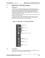
Page 119: ... of this document is a partial list of Internet links to useful information about Ethernet and TCP IP networking The Remote Programmer Access switch future feature will allow you to enable disable MMC running over Ethernet The DIAG LED goes on briefly while the diagnostic tests are running shortly after power is applied Figure 6 1 MMC Ethernet TCP IP Option Module 6 2 Connections A serial cable is...

Page 120: ...et up your Ethernet TCP IP system The table below summarizes the specifications IEEE 802 3 for the Ethernet connection available on the MMC Ethernet TCP IP module Table 6 1 Ethernet Port Specifications Item Specification Type of Cable Category 3 or 5 5 recommended UTP shielded twisted pair Shielded category 5 cable is optional Connection RJ 45 Topology Star Distance 100 M 328 ft between transceive...

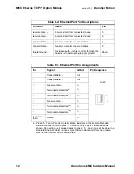
Page 121: ...he maximum length of the twisted pair cable segment is 100 M 328 ft NOTE The connector is also suitable for shielded cable and will ground the shield to the chassis Pin descriptions for are provided in Table 6 2 Pin assignments are provided in Table 6 3 The available Ethernet Port to Ethernet Device cables are described in Table 6 4 Node Node Node Shielded 10Base T Twisted Pair Maximum segment len...

Page 122: ...int ground Shell Table 6 3 Ethernet Port Pin Assignments Pin Signal In Out Pin Sequence 1 Transmit Data Out RJ 45 2 Transmit Data Out 3 Receive Data In 4 Termination Resistors a a Pins 4 5 7 and 8 are tied to termination resistors on the Module Standard Ethernet cables contain 8 wires The Module only uses 4 of these wires as shown Connecting the 4 unused wires to pins 4 5 7 and 8 as will be done i...

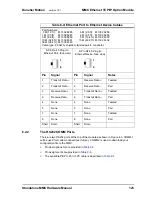
Page 123: ... to Ethernet Device Cables Part Numbers 3 M 1 0 ft M 1302 8285 6 M 2 0 ft M 1302 8286 1 M 3 3 ft M 1302 8287 2 M 6 6 ft M 1302 8288 3 M 9 8 ft M 1302 8289 5 M 16 4 ft M 1302 8300 10 M 32 8 ft M 1302 8301 15 M 49 2 ft M 1302 8302 30 M 98 4 ft M 1302 8303 Cable type 28 AWG shielded twisted pair 8 conductor 8 Pin RJ 45 Plug to Ethernet Port face view 8 Pin RJ 45 Plug to Ethernet Device face view Pin ...

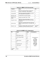
Page 124: ...en 3 Vdc 4 Request to send RS232 level signal that indicates to the con nected serial device that it can transmit data to the Module 7 Clear to send RS232 level signal that indicates to the Module that it can transmit data to the connected serial device 8 Shield Ground Provides a path for shield current through the chassis to an external single point ground Connector Shell Table 6 6 COMM Port Pin ...

Page 125: ...der the DIAG LED as shown below Table 6 7 COMM Port to PC Cable Part Number M 1302 8250 Length 4 M 13 ft Cable type 24 AWG shielded twisted pair 4 conductor 9 Pin female D sub to COMM Port face view 9 Pin female D sub to PC COM Port face view Pin Signal Pin Signal Notes 2 Receive Data 3 Transmit Data Twisted 3 Transmit Data 2 Receive Data Pair 5 Signal Ground 5 Signal Ground Shell Drain Shell Drai...

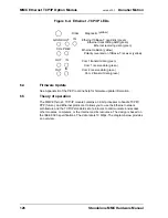
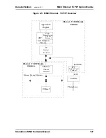
Page 126: ...network architecture and the TCP IP standard set of protocols to communicate and access other modules computers or the Internet and its resources The design is based on the IEEE 802 3 specifications The data rate is 10 Mbps The diagram below provides an overview DIAG IN OUT GDLNK IN OUT IN OUT PREV COL Diagnostic Ethernet receiving data green Ethernet transmitting data green Ethernet 10Base T good...

Page 127: ...C Ethernet TCP IP Overview 10Base T PPP Modem Ethernet IP TCP Application Program Transmission Control Protocol Internet Protocol Phone Line Point to Point Protocol Network Interface Software Ethernet TCP IP Module Ethernet Physical Mediums UDP User Datagram Protocol FUTURE Ethernet TCP IP Module Hardware RS232 ...

Page 128: ...73 23 EEC 89 336 EEC 92 31 EEC 93 68 EEC by conforming to the fol lowing standards EN 50081 2 1993EMC Generic Industrial Emis sions EN 50082 2 1995EMC Generic Industrial Immu nity EN 61131 2 1994 A11 1996 Low voltage direc tive requirements for programmable controllers Operates with emissions below EN55011 CISPR 11 Class A limits Immune to Electrostatic discharge 4K V contact mode 8K V air dischar...

Page 129: ... com cable Basics types html http www jdltech com solutions Standards_Terms cfm http www jdltech com solutions LAN_terms cfm http www datatech com hot w96_2 htm http www standards ieee org catalog IEEE802 3 html http www 3com com nsc glossary main htm http www alliedtelesyn com prd_tran htm microtrans http www lothlorien net collections computer ethernet_frames html http www lantronix com htmfiles...

Page 130: ...130 Standalone MMC Hardware Manual MMC Ethernet TCP IP Option Module version 15 1 Danaher Motion ...

Page 131: ...pecific configuration software in an external PC This file must be downloaded via the RS232 configuration port to the DeviceNet module prior to initial operation Two indicator LEDs IN OUT are connected to this configuration port Directly above the DeviceNet port are two LEDs that provide operation information Network Status and DeviceNet Scanner Status The DIAG LED goes on briefly while the diagno...

Page 132: ...odes may be attached to the DeviceNet scanner module Figure 7 2 DeviceNet Connections PC connected to RS232 port for downloading file generated with MMC DeviceNet Danaher Motion DeviceNet configuration DeviceNet Node DeviceNet Node DeviceNet Node To DeviceNet Trunk To DeviceNet Trunk CNFG NETWORK DeviceNettm DIAG PORT IN OUT CNFG PORT STATUS SCANNER STATUS DeviceNetTM PORT software ...

Page 133: ...specifications Only use DeviceNet compliant cable such as Belden 3084A thin wire and Belden 3082A thick wire 7 2 2 The Configuration RS232 Port There is an RS232 port on the lower front of the module as shown in Figure 7 1 on page 131 This is used to connect to a PC in order to download a file representing your DeviceNet network Pin Signal Name Standard Wire Colors 1 V black 2 CAN_L blue 3 Shield ...

Page 134: ...eviceNet Port Network status None OFF Off line Green ON On line and connected to at least one node Flashing On line but connection nodes not established Red ON Unrecoverable Fault duplicate MAC ID check failed critical bus fault etc Flashing I O connections in timed out state or other Recoverable Fault Scanner status Green OFF No power or else reset assert ed ON Scanner OK and active Flashing Scan...

Page 135: ...n the memory image and the declared variables in the LDO To ensure that a given location in the memory image is connected to a variable in the LDO and to the corresponding data in the DeviceNet node the same tag name or label must be used For example when running the configuration software PROX_SW1 could be used as the name for the boolean bit representing a DeviceNet proximity switch s logic stat...

Page 136: ...tandards EN 50081 2 1993EMC Generic Industrial Emis sions EN 50082 2 1995EMC Generic Industrial Immu nity EN 61131 2 1994 A11 1996 Low voltage direc tive requirements for programmable controllers Operates with emissions below EN55011 CISPR 11 Class A limits Immune to Electrostatic discharge 4K V contact mode 8K V air discharge per EN61000 4 2 RF electromagnetic fields per EN61000 4 3 ENV 50141 and...

Page 137: ...pecific configuration software in an external PC This file must be downloaded via the RS232 configuration port to the Profibus module prior to initial operation Two indicator LEDs IN OUT are connected to this configuration port Directly above the Profibus port are two LEDs that provide operation information Network Status and Profibus Scanner Status The DIAG LED goes on briefly while the diagnosti...

Page 138: ...the Profibus scanner Up to 125 other Profibus Nodes using repeaters may be attached to the Profibus scanner module Figure 8 2 Profibus Connections PC connected to RS232 port for downloading file generated MMC Profibus with Danaher Motion Profibus Profibus Node Profibus Node Profibus Node To Profibus Trunk To Profibus Trunk configuration software CNFG NETWORK Profibus DIAG PORT IN OUT CNFG PORT STA...

Page 139: ...connect to a PC in order to download a file representing your Profibus network Table 8 1 Pinout for Profibus Port Pin Signal Name Note It is strongly recommended that you use Profibus Sub D connectors with switchable ON OFF termination such as Siemens 6ES7 972 0BA11 0XA0 or 6ES7 972 0BB11 0XA0 Only use Profibus type A cable such as Belden 3079A or Siemens 6XV1 830 0AH10 1 Chassis ground 2 reserved...

Page 140: ...tion software generates two files One file is downloaded to the Profibus module through its RS232 serial port The other file is used by PiCPro to establish the relationship between the memory image and the declared variables in the LDO To ensure that a given location in the memory image is connected to a variable in the Table 8 3 Description of Profibus Port LEDs Port LED Color State Definition Pr...

Page 141: ..._SW1 must also be used for the corresponding variable in your LDO The Profibus scanner module provides DP master Class 1 functionality only This includes DP multi master support token passing and cyclic slave communications It does not support DP master Class 2 sync and freeze modes nor extended DP functions NOTE The Danaher Motion Profibus configuration software Danaher Motion Part No M 1300 7794...

Page 142: ... forming to the following standards EN 50081 2 1993EMC Generic Industrial Emissions EN 50082 2 1995EMC Generic Industrial Immunity EN 61131 2 1994 A11 1996 Low voltage directive requirements for programmable controllers Operates with emissions below EN55011 CISPR 11 Class A limits Immune to Electrostatic discharge 4K V contact mode 8K V air discharge per EN61000 4 2 RF electromagnetic fields per E...

Page 143: ... not declared in Servo Setup D A converter feedback channels on board DC I O When a channel is declared as an Axis in Servo Setup the typical signals needed to interface to an analog drive are provided by the MMC Axis I O Option Module The drive command is in the form of an analog voltage 10V Feedback is accepted from quadrature type encoders with differential outputs Digital I O 24 Vdc is used fo...

Page 144: ... Option Module version 15 1 Danaher Motion Figure 9 1 Locations of Input Output Encoder Pins 44 Pin AUX Input 15 pin Axis Connectors 1 Analog Output 1 Encoder Input 2 DC Outputs 1 DC input 12 DC Inputs 5 Fast DC Inputs 1 Encoder Input 1 Analog Input ...

Page 145: ... 61131 2 1994 A11 1996 Low voltage directive requirements for programmable controllers Operates with emissions below EN55011 CISPR 11 Class A limits Immune to Electrostatic discharge 4K V contact mode 8K V air discharge per EN61000 4 2 RF electromagnetic fields per EN61000 4 3 ENV 50141 and ENV50204 Electrical fast transients per EN61000 4 4 Magnetic fields per EN61000 4 8 Refer to the EMC Guideli...

Page 146: ...e range 10 VDC Maximum output current 1K Ω load 10 mA Power on output voltage 0 V 100 mV Scan loss output voltage 0V 100 mV Accuracy 0 375 of FSR Drift 50ppm C Update rate 68 µsec Aux Port Analog Input Input channel 1 Resolution 12 bits Input voltage range 10 V Accuracy 0 2 of FSR Sample rate 100 µsec Common mode filter 3 dB 10 K Hz Differential mode filter 3 dB 475 Hz ...

Page 147: ...DC Guaranteed off voltage 5 VDC Turn on off time 1 ms Axis Port Aux Port DC Inputs Configuration The auxiliary inputs are divided into two groups of six inputs Each group can be configured for sourc ing or sinking The axis inputs have one input per axis Each input can be configured for sourcing or sinking Operates with IEC Type 1 inputs per IEC 1131 2 Input voltage Nominal 24 VDC maximum 30 VDC Gu...

Page 148: ...rdware Manual MMC Axis I O Option Module version 15 1 Danaher Motion Aux Port 5 Vdc Output 5 VDC 150 mA maximum current available Connections to this point should be over short distances and away from electric noise signals ...

Page 149: ...tion the first input of each group of 8 can be programmed to provide a processor interrupt on either a low to high or high to low input transition Each connector also provides 16 source only 24 Vdc outputs Each output is capable of sourcing 250 ma and is protected from both short circuits as well as overloads The Diagnostic light at the top of the module labeled DIAG turns on briefly when power is...

Page 150: ...1 MMC 32 In 32 Out Option Module 10 2 Connections Operation The two 44 pin HD male D sub I O connectors labeled GEN I O A and GEN I O B on the front of the Module provides connection between the user I O devices the Diagnostic Light DIAG General I O Connector A GEN IO A General I O Connector B GEN IO B ...

Page 151: ...plied 24 Vdc power nominal that supplies the necessary current to power DC Outputs 9 16 18 32 24 Vdc Common for Outputs 1 16 User supplied 24 Vdc Common that supplies the return path for the DC Output logic cur rent 33 DC Inputs 1 8 Nominal 24 Vdc Inputs Sink or Source In puts 1 8 23 30 Sink Source select pin for DC Inputs 1 8 To make DC Inputs 1 8 sourcing inputs 24 Vdc applied to the DC Input tu...

Page 152: ...UT9 Out 10 DCOUT10 Out 11 DCOUT11 Out 12 DCOUT12 Out 13 DCOUT13 Out 14 DCOUT14 Out 15 DCOUT15 Out 16 DCOUT16 Out 17 DCOUTPWR1 In Pin Signal In Out 18 DCOUTPWR2 In 33 DCOUTC In 19 20 N C N A 34 N C N A 21 DCSS1 In 35 DCSS2 In 22 N C N A 36 N C N A 23 DCIN1 In 37 DCIN9 In 24 DCIN2 In 38 DCIN10 In 25 DCIN3 In 39 DCIN11 In 26 DCIN4 In 40 DCIN12 In 27 DCIN5 In 41 DCIN13 In 28 DCIN6 In 42 DCIN14 In 29 D...

Page 153: ...26 DCIN4 White Pair 7 DCOUT7 Black Twisted 28 DCIN6 Green Twisted 8 DCOUT8 Blue Pair 29 DCIN7 Blue Pair 9 DCOUT9 Black Twisted 31 DCOUTPWR1 Green Twisted 10 DCOUT10 Yellow Pair 32 DCOUTPWR2 Yellow Pair 11 DCOUT11 Black Twisted 33 DCOUTC Green Twisted 12 DCOUT12 Brown Pair 34 None Brown Pair 13 DCOUT13 Black Twisted 35 DCSS2 Green Twisted 14 DCOUT14 Orange Pair 36 None Orange Pair 15 DCOUT15 Red Tw...

Page 154: ... a The Breakout Box for the General I O connector can be attached to the GEN I O port on the MMC Control and on the GEN I O A and GEN I O B ports on the MMC 32 In 32 Out Expansion module The pinouts on the terminal strip inter face provide a one to one transfer of the signals from the connector to the respective pin s on the terminal block The connector pins marked with the ground symbol on the sc...

Page 155: ...approximately 100 ms regardless of ladder activity After 100 ms the ladder again controls the outputs In addition each output is protected with internal clamping diodes Without clamping high voltage transients kickback from inductive loads might damage the module For safety reasons all outputs turn off no current flow when a scan loss condition occurs For more information on DC output operation re...

Page 156: ...re 10 3 Gen I O Port Output Connections 1 To MMC GENERAL CONNECTOR DC OUTPUT PINS 24 Vdc Power Supply _ SPG Common DCOUT1 DCOUT2 DCOUT3 DCOUT4 DCOUT5 DCOUT6 DCOUT7 DCOUT8 DCOUT9 DCOUT10 DCOUT11 DCOUT12 DCOUT13 DCOUT14 DCOUT15 DCOUT16 LOAD 3 5 7 9 11 13 15 DCOUTPWR1 DCOUTPWR2 DCOUTC 33 17 31 18 32 ...

Page 157: ...S pin DCSS1 for Group A DCSS2 for Group B to IO24C for a sourcing configuration Connect the DCSS pin DCSS1 for Group A DCSS2 for Group B to 24 Vdc for a sinking configuration An example of connecting input devices in both a sink and source configuration is shown in Figure 10 4 In addition the first input of each Group Input 1 of Group A and input 9 of Group B can be programmed to provide a process...

Page 158: ...on Figure 10 4 General Input Connections 23 MMC GENERAL CONNECTOR DC INPUT PINS DCIN1 DCIN2 DCIN3 DCIN4 DCIN6 DCIN7 DCIN8 25 27 29 DCSS1 21 SINK 37 DCIN9 DCIN10 DCIN11 DCIN12 DCIN14 DCIN15 DCIN16 39 41 43 DCSS2 SOURCE DCIN5 DCIN13 35 To 24 Vdc Power Supply _ SPG SWITCHING DEVICE 24V Common ...

Page 159: ...al 24 VDC maximum 30 VDC Guaranteed on voltage 15 VDC Guaranteed off voltage 5 VDC Turn on off time 1 ms DC Outputs Number of Outputs 32 outputs 16 on each connector Input voltage Nominal 24 VDC 30 VDC maximum Configuration On each of two connectors there are two groups of eight solid state switches Protection of logic circuits Optical isolation between the logic and field side di ode transient su...

Page 160: ...z constant amplitude 15 mm 57 2000 Hz acceleration 2 g Shock per IEC 68 2 27 Four shocks per axis 15g 11 msec CE Marked Conforms to Directives 73 23 EEC 89 336 EEC 92 31 EEC 93 68 EEC by conforming to the following standards EN 50081 2 1993EMC Generic Industrial Emissions EN 50082 2 1995EMC Generic Industrial Immunity EN 61131 2 1994 A11 1996 Low voltage directive re quirements for programmable co...

Page 161: ...n of conformity 11 2 Background on Low Voltage Compliance In order to market products in the European Union after January 1 1997 the low voltage directive EU Directive 73 23 EEC must be met The intention of the directive is to assure user safety under normal operating and fault conditions The directive includes the use of certain warning labels and user instructions It establishes limits to preven...

Page 162: ...ompared to a household or office environment Since it is more expensive to reduce the emissions from higher power equipment than to increase the immunity the emission limits allowed in industrial environments are higher than for household or office environments Vice versa for immunity because of the higher emission limits in industrial environments the immunity requirements are more strict than fo...

Page 163: ... EN 61131 2 1994 A11 1996 Low Voltage Requirements for Programmable Con trollers A statement of compliance will be made with the letters CE on the product but will be valid only if the equipment is properly installed 11 7 Changes to the PiC Products Danaher Motion PiC products had originally been designed with a high level of noise immunity and tested according to standards such as NEMA showering ...

Page 164: ... figure on the left below illustrates the connection method before EMC compliant products were available The figure on the right illustrates the recommended connections when using EMC compliant products On the right note that the SPG connection has been eliminated and that a capacitor is connected to the 24V DC supply Figure 11 2 Connections for EMC Compliance There is now a provision for shield t...

Page 165: ...irement for emissions and immunity fiber optics must be used for I O expansion Although the control will pass the electrical fast transient test on incoming power lines users may still want to use a power line conditioner As a general precaution do not operate transmitters arc welding equipment or other high noise radiators within one meter of a PiC enclosure that has the door open Continue to equ...

Page 166: ...llowing For CE EMC modules do not connect the SPG terminal or SHIELD terminals to the system s Single Point Ground For Non CE EMC modules connect the SPG terminal or a SHIELD terminal to the system s Single Point Ground CE EMC CSM and RSM Modules Using a CE EMC CSM RSM or CSM CPU PiC90 with certain Non CE EMC analog modules may cause intermittent operation Follow these guidelines for determining t...

Page 167: ...es If your rack does not contain one or more Non CE EMC modules that perform D A conversion or provide an Encoder interface you may use either a CE EMC or Non CE EMC CSM RSM or CSM CPU PiC90 NOTE For a system to be CE EMC compliant all modules and backplanes must be CE EMC compliant ...

Page 168: ...168 Standalone MMC Hardware Manual CE and EMC Guidelines version 15 1 Danaher Motion 11 9 Declarations of Conformity ...

Page 169: ...Standalone MMC Hardware Manual 169 Danaher Motion version 15 1 CE and EMC Guidelines ...

Page 170: ...170 Standalone MMC Hardware Manual CE and EMC Guidelines version 15 1 Danaher Motion ...

Page 171: ...Standalone MMC Hardware Manual 171 Danaher Motion version 15 1 CE and EMC Guidelines ...

Page 172: ...172 Standalone MMC Hardware Manual CE and EMC Guidelines version 15 1 Danaher Motion ...

Page 173: ...he system bus to the application program which uses these logic states to control program flow The logic side of the input is optically isolated from the field side The shaded blocks in Figure A 1 below show the limits specified by the IEC The lines show the maximum and minimum V I of the inputs in this module The voltage current curve in this graph shows that the input module is well within the I...

Page 174: ...n an output is energized represented by a closed switch current passes through the load into the common line When the output is de energized represented by an open switch current stops and the inductive field collapses The state of the outputs is controlled by the CPU This creates a reverse voltage across the load called kickback which tries to continue the IMPORTANT Switching devices can sometime...

Page 175: ...ude 7272 75183 8830 75114 9614 26LS31 or equivalent A quadrature encoder sends square wave type signals When the shaft rotates at a constant velocity the A and B outputs are square waves and are at the same frequency However they are out of phase with each other by 90 When the encoder shaft rotates in one direction each A pulse leads the corresponding B pulse by 90 When it rotates the other direct...

Page 176: ...ext index pulse after the required transition of the fast input Each of the five 24 bit latches has a fast 24 VDC input associated with it Each input is optically isolated This input is intended to receive a signal from a device other than an encoder It is typically used for referencing or synchronization purposes Fast input characteristics include the detection of a signal occurs faster than it d...

Page 177: ... MMC Control 115 in Standalone MMC Control 87 block I O port Standalone Digital MMC Control 98 Standalone MMC Control 43 breakout box isolated encoder 77 C CE guidelines 161 codes diagnostic error 31 com ports Ethernet module 123 Compliance to low voltage directive 161 configuration port DeviceNet module 133 Profibus module 139 conformance EMC directive 163 low voltage directive 163 conformity dec...

Page 178: ...9 Ethernet port specifications 120 firmware update 126 front view 119 introduction 119 lights 125 operations 126 specifications 128 useful Internet links 129 Ethernet port Standalone Digital MMC Control 110 F fast inputs aux I O port 79 fast transient voltage 162 features Standalone Digital MMC Control 95 Standalone MMC Control 33 firmware update Ethernet module 126 front view 32In 32Out module 15...

Page 179: ... 134 encoder inputs 175 Ethernet module 126 MMC Control 17 Profibus module 140 safety 14 SERCOS motion 83 Standalone Digital MMC Control 97 option module adding 18 dimensions 20 mounting 18 overview Standalone Digital MMC Control 95 Standalone MMC Control 33 P part numbers Standalone Digital MMC Control 117 Standalone MMC Control 89 PiCPro port Standalone Digital MMC Control 108 Standalone MMC Con...

Page 180: ...ons 97 digital link ports 112 Ethernet port 110 features 95 front view 96 introduction 95 operation 97 overview 95 part numbers 117 PiCPro port 108 power connector 114 power supply requirements 96 specifications 117 user port 102 Standalone MMC Control 33 analog motion connections 62 operation 62 analog servo board 36 aux I O port 72 analog input 83 DC inputs 81 encoder input 82 fast inputs 79 axi...

Page 181: ...n 15 1 Index U user port Standalone Digital MMC Control 102 Standalone MMC Control 47 V voltage fast transient 162 W warning label danger warning caution 13 hazard 12 Web Address 182 wiring application 26 EMC compliant 26 for EMC compliance 164 guidelines 26 ...

Page 182: ...please contact us North America Danaher Motion Customer Support North America E mail glmotion support danahermotion com Phone In the United States telephone 800 558 4808 Outside the United States telephone 920 921 7100 Fax 920 906 7669 Web site www glcontrols com Europe Danaher Motion Customer Support Europe E mail glmotion support danahermotion com Phone 44 0 1525 243 243 Fax 44 0 1525 243 244 We...

Reviews: