17. Conexión entre el acople del barril y el barril de
cerveza:
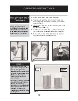
Antes de hacer (abrir) la conexión entre
el acople del barril y el barril de cerveza,
asegúrese de que la canilla de la torre de cerveza
esté en la posición de cerrado. (con la manija
derecho hacia atrás). Para conectar el tanque, tire
de la manija del acople del barril y empuje hacia
abajo hasta que se trabe en su lugar. Escuchará
que la manija hace ‘clic’ en su posición final hacia
abajo.
Ver Fig. 9.
18. Apertura de la válvula principal del cilindro de
CO
2
:
Antes de abrir la válvula principal ubicada
arriba del cilindro de
CO
2
. Asegúrese de que la
válvula de corte "secundaria" ubicada en el caño
inferior del regulador esté cerrada.
Ver Fig. 10.
NOTA:
Cuando la válvula secundaria (manija) está
en posición horizontal (este/oeste), la válvula está
cerrada. Cuando la válvula secundaria (manija) está
en posición vertical (norte/sur), la válvula está
abierta. Para abrir la válvula principal del cilindro de
CO
2
, gire (lentamente) la válvula principal en sentido
contra horario hasta que se abra completamente.
Notará que las agujas de los dos indicadores
comienzan a moverse.
19. Ajuste del regulador de
CO
2
:
El regulador de
CO
2
tiene dos medidores de presión.
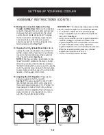
Ver Fig. 12.
El medidor superior #1 indica la presión "BAJA"
(dentro del barril) y debe ajustarse a la presión de
trabajo correcta entre 10 ~ 12 psi/libra. El medidor
inferior #2 indica la presión "ALTA" (del cilindro de
CO
2
) y no se puede ajustar. El indicador de alta
presión también funciona como un indicador de
combustible avisándole cuando el cilindro de
CO
2
necesita ser recargado.
IMPORTANTE:
La presión interna de trabajo del barril
de cerveza debe ajustarse y mantenerse entre 10 y 12
psi/libra. Para ajustar el indicador de "baja" presión:
•
Afloje la tuerca de traba de ajuste #3 con una llave
ajustable.
Ver Fig. 11.
•
Con un destornillador plano, gire el tornillo de ajuste
del regulador #4.
Ver Fig. 11.
El giro del tornillo en
sentido horario aumentará la presión. El giro del
tornillo en sentido contra horario disminuirá la presión.
•
Al alcanzar la presión de trabajo deseada, vuelva a
ajustar la tuerca de traba de ajuste #3
•
Ahora está listo para servir cerveza fría.
Fig. 7
Fig. 8
Fig. 9
2
1
4
5
6
3
Llave de paso
Secundaria
PREPARACIÓN
INSTRUCCIONES DE ARMADO (CONT.)
52
ASSEMBLY INSTRUCTIONS (CONT’D)
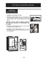
5. Installation of C0
2
Air Line Hose to Regulator:
Attach one end of the (red) air line hose to the
hose barb connection on the CO2 regulator.
Secure hose by using one of the two (self locking)
black plastic snap on clamps provided. (use pliers
to snap the clamp tight to
ensure t
hat there are no
leaks)
See Fig. 5
6. Installation of the Beer Tower Gasket:
Position
the rubber (beer tower) gasket directly on top of
the cabinet aligning all four holes in the gasket
with the four holes on the cabinet.
7
.
Installation of the Beer Tower:
Unravel the beer
line (hose) from the tower and insert the beer
line and nut through the gasket and into the
cabinet. Align the four holes in the base of the
beer tower, gasket and bayonet. The beer faucet
should be facing the front of the cabinet. (6:00
o'clock position) Using a Phillips Screwdriver,
attach the beer tower to the cabinet using the four
machine screws provided and tighten firmly.
8 . Installation of the Beer Tower Faucet Handle:
Screw the black faucet handle (clockwise) onto
the beer tower faucet. (hand tighten only)
9. Installation of the Keg Coupler: IMPORTANT
NOTICE;
Make sure the pull handle of the
keg coupler is in the "upward" (closed) position
before installing on the beer keg.
See Fig. 6
Insert
the keg coupler into the locking neck of the beer
keg and apply a 1/4 turn clockwise to lock into
position.
10. Installation of the CO
2
Air Line Hose to the
Keg Coupler:
Attach the open end of the (red) air
line hose to the hose barb connection on the keg
coupler. Secure hose by using the remaining (self
locking) plastic snap on clamp provided. (use pliers
to tighten clamp and ensure there are no leaks)
11. Installation of the Beer Line Hose to the Keg
Coupler:
Screw the beer line nut onto the keg
coupler and hand tighten firmly.
IMPORTANT
NOTICE:
The black rubber washer provided must be
installed inside the beer line connection nut before
connecting the beer line to the keg coupler.
Fig. 5
SETTING UP YOUR KEG COOLER
11
Fig. 6

