background image


4

3

01-6

01-7

02

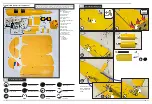
Assemble the Wing

F3

F3

F2

F2

F2

F2

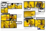
02-1

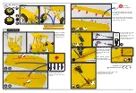
Install the servo into the 

prepared hole. Install the 

servo's link rod. Test the 

position and open hole 

(15mm).

Add some lubricating oil in the joint 

of needle type hinge.(Avoid the glue 

stuck dead.)

Before install and fasten needle type 

hinge, please confirm the surface can 

swing freely in advance.

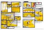
Install long servo horn screws.

Install the round servo plate 

on the servo arm, then 

install the servo arm on the 

aileron link rod.

Adjust the length of link rod 

by revolving connectors.

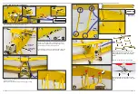
Install according to the number, 

please note the arrowhead 

direction, and fasten with epoxy 

adhesive.

Self-locking nut

Please don't fasten 

in advance,fasten 

before final adjust-

ment.(Step 2-15)

Upper wing underside

Lower wing topside

Pay attention to the arrowhead direction.

Pay attention to the arrowhead direction.

02-2

02-3

02-6

02-5

02-8

02-9

Epoxy glue

Epoxy glue

1

2

3

4

1

2

3

4

02-4

 lubricating oil

1. Install link rod on the servo horn's screw.

2. Adjust suitable link rod length.

3. Install servo arm on the servo.

x2

x2

x2

Epoxy glue

OIL

E

G1

B1

B2

M4*48mm+self-locking nut

15mm

M3

02-7

Add a little CA glue into 

the drill hole, tighten 

screws after the glue dries.

1

2

3

Summary of Contents for Tiger Moth DH82 2.15M

Page 1: ...to ensure the best flight performance Double check the inside of the fuselage make sure all the equipments are correctly connected Check the heat shrink covering material s surface Make certain all sc...

Page 2: ...le times x2 01 Assemble the Landing Gear A B1 B2 C D E F1 F2 F3 F4 G1 G2 H I1 I2 I3 J K L M N O P Q 01 1 01 2 01 3 01 4 01 5 I1 I4 I4 I3 I2 I3 I4 Self locking nut Screw Nut Nut Nut Nut Here please use...

Page 3: ...rod by revolving connectors Install according to the number please note the arrowhead direction and fasten with epoxy adhesive Self locking nut Please don t fasten in advance fasten before final adju...

Page 4: ...ing 02 15 M3 18mm Self lock nut 02 13 02 12 Epoxy glue x4 Mark Mark X01 Preassemble X01 on the fuselage fasten with screw as picture shown Then mark along the edge Take out after mark Install X01 on t...

Page 5: ...tay wire Install other half wing with the same steps in above assemble stay wire symmetrically About the installa tion way of stay wire s stabilizer rod please see picture Details 4 All wires through...

Page 6: ...le to the middle position fasten with nut M4 48mm spacer self locking nut 05 3 Assemble the connecting parts on the two ends of screw pole Control the rudder with the fuselage s inside servo by double...

Page 7: ...allation for servo arm and link rod please refer to steps 02 6 Here engine installation only for referance You can adjust your installation details according to your engine Instrument panel installati...

Page 8: ...ger Flap take off 15 20 Landing 20 40 Some special models will have V tails flaps leading edge wings etc which can be used as a reference for conventional flight angles If you do not confirm and there...

Reviews: