8
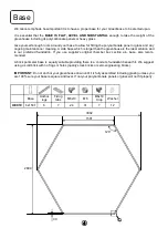
BASE
Base dimensions and recommendations. Ensure that your base is level as this will make assembly of
the building, especially the glazing of the roof much more straight forward.
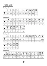
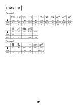
PARTS LIST
Most components should have a code punched into their metal surface. Identify and
separate all like for like components prior to assembly. The parts lists also separates parts into the various
sections Package1 - Package 7 shown above. Parts can also be identified by their profile pictures and
stated lengths etc..
PREPARATION
The frame is assembled by feeding square headed bolts, either 10mm or 15mm in
length into the slots on glazing bars and then locating those bolts through holes in purlings and cills, etc…
Twist in (rectangular) crop headed bolts are also used towards the end of construction to attach compo-
nents to the frame when the glazing bar slots are no longer exposed at the ends. On the door frame posts
#7530 & #7531 and door horizontals #7520 & #7521 & #7522, nuts are slid into the channel rather than
bolts to ensure minimum protrusion. Tools required / recommended.
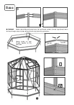
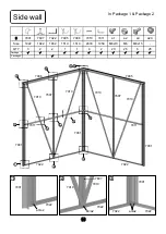
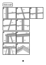
SIDE WALL
Use 10mm and 15mm bolts to join the components (note how the head of the bolt slides into each glazing
bar during construction). The correct choice of bolt is highlighted with a number #a1/#a3 in each of the dia-
grams.
Do the same for Rear wall & Front wall later.
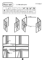
JOINING TWO SIDE WALL SECTIONS TOGETHER 1
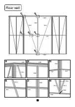
------REAR WALL
Use the gutter #7906 and sill #7022 and side horizontal bracing bar # 7911 to join two side wall together
on rear wall, It is a good idea to tie some step ladders to the sides to support them if you do not have
anyone to hold them for you.
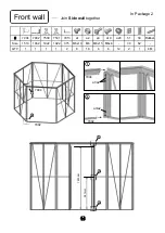
JOINING TWO SIDE WALL SECTIONS TOGETHER 2
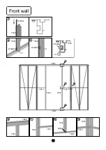
------ FRONT WALL
Use the gutter #7904 and sill #7902 to joining two side wall together on front wall.
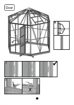
IMPORTANT: The front wall contain a door posts #7530 & #7531, Please also ensure that the door rub-
bers are inserted into door frame posts # 7530 and #7531.
#7531 houses the door strike #L9 by sliding NUTS into the provided channel. #7530 houses the door
hinges #h1 /#h3 which are fitted in a similar way to the strike using the low protrusion #a19 round headed
bolts.
The strike and hinge components are packed with the other door components Package 5. Ensure that the
strike is in the correct orientation with the catch hole uppermost. The height the hinges are set at is not
important at this stage, they will be set in section of door assembly later.
ROOF
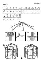
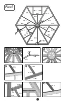
Assemble 6 roof corner bars #7914 on hexagonal roof bracket #7992 . Please note #7914 overlap bracket
by distance of
42
mm. tighten all bolts.
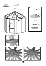
Then lift the assembly onto the roof, Herein you should use step ladders. Loosely Connect the roof corner
bars to the eaves at all 6 corners.
Please note: At this stage you need to decide where your roof vents are positioned so that you could insert
an extra bolt into each roof corner bar either side of a vent opening.
Connect 3 roof vent hinge beam #7921 to roof corner bar with joining plate #m3.
Summary of Contents for Orangery
Page 1: ...Manual for Orangery hexagonal glass 7 2 m 18 12 2020...
Page 2: ...Walk in Greenhouse Assembly Instructions For Single Hinged Door Orangery...
Page 19: ...18 9 9 a24 a25 7991 7992 7993 7994 Roof 10 10 p10 7914 open close...
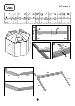
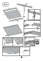
Page 21: ...20 Vent 7952 7057 5 5 6 7952 7057 a7 a10 7952 7924 5 7951 7924 7924 7952 7 7 6 p11 9 p3 a4 8...
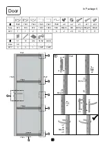
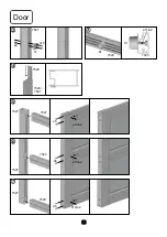
Page 24: ...23 Door 8 L9 a19 a2 7531 8 9 10 10 a11 m12 a9 a2 s2 h7 9...
Page 26: ...25 Silicone Waterproof Alu Foil tape 100mm x 6pc 25 33...
Page 27: ...26 4mm Glass...


