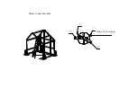
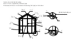
Dancover Titanium Tent, Manual
The Dancover Titanium Tent is a durable and versatile outdoor shelter, perfect for various events and gatherings. This high-quality tent comes with a comprehensive user manual, available for free download at 88.208.23.73:8080. Ensure a seamless experience with this essential manual, featuring step-by-step instructions and insightful tips.
Share
Download


Reviews:
No comments
Related manuals for Titanium Tent

594900
Brand: Wanderer Pages: 4

15-728851
Brand: Ombréa Pages: 83

26800
Brand: Gazelle Pages: 4

RT1
Brand: Boss Aluminium Pages: 8

33046
Brand: Wenzel Pages: 2

EliteHC 360S
Brand: Mammoth Tents Pages: 2

Atlantis G-Gutter
Brand: FenWall Pages: 2

84C-262
Brand: Outsunny Pages: 10

Hammerfest 4 Protect
Brand: Outsunny Pages: 2

Lodge 200 Motor
Brand: SunnCamp Pages: 2

F10 Series
Brand: Vango Pages: 6

Bora v2
Brand: Kathmandu Pages: 20

The Greenbriar
Brand: ShadeTree Pages: 10

PEAK TWIN DOME
Brand: OZtrail Pages: 16
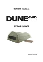
OUTBACK XL SWAG
Brand: Dune 4WD Pages: 8

GT1010
Brand: PARRY Pages: 59

Solo Up
Brand: Suntime Pages: 9

Hitch Tent
Brand: Rubicon Expedition Products Pages: 21


