3. Preparation
3.1.
General preparations
Check the acoustical and mechanical set up with the ArrayCalc array
calculator and prepare enough print outs for each array.
Using the plan, the riggers are able to set up the suspension points, the
securing points and the chain hoists.
WARNING!
The working load limit of the chain hoists and their
suspension points has to be high enough to carry the
total system weight.
As during a dual hoist set up the motors might not
always be synchronized each of the suspension points
has to be able to carry the total system weight.
When on site first clear the working areas, check that the hoists are
exactly in the specified position, the chains are not twisted and there is
enough space to set up and lift the array.
3.2.
Inspections
All system components must be inspected for faults before use. This also
includes the loudspeaker and in particular the rigging parts of the
cabinets.
Damaged components must be withdrawn from use immediately. Please
pay attention to section 6. Care and maintenance / Disposal on page
31 of this manual.
3.3.
J-Series Locking pins
LOCK PIN
SECURELY
BEFORE LIFTING
CAUTION
ONLY UNLOCK FOR
DISASSEMBLY ON
GROUND
WARNING!
The steel wire between the locking pins is not meant to
suspend a cabinet or carry any load. The cabinet's weight
must only be carried by the Front and Splay links in
conjunction with front and rear rigging strands of the
loudspeaker cabinets
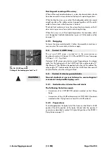
Fig. 10: J-Series Locking pins, Quicklock
Assembly
1. Pressing the button
[B]
releases the locking mechanism allowing
insertion through the respective links or sockets.
2. Releasing the button after the pin is inserted and fixed in place the
locking mechanism will be locked. A groove
[G]
(Fig. 10) in the bolt
of the pin indicates that it is properly locked.
J-Series Rigging manual
(1.3 EN)
Page 11 of 34
Summary of Contents for J Series
Page 1: ...J Series Rigging manual 1 3 EN...
Page 33: ......


