Rigging concept and components
2.3 Locking pins
The KSLi Mounting frames and the adapter are equipped with two
types of Locking pins.
WARNING!
Potential risk of personal injury and/or
damage to material!
Ensure all Locking pins are fully inserted and securely locked
before lifting any load.
For this purpose, briefly pull the Locking pin towards you.
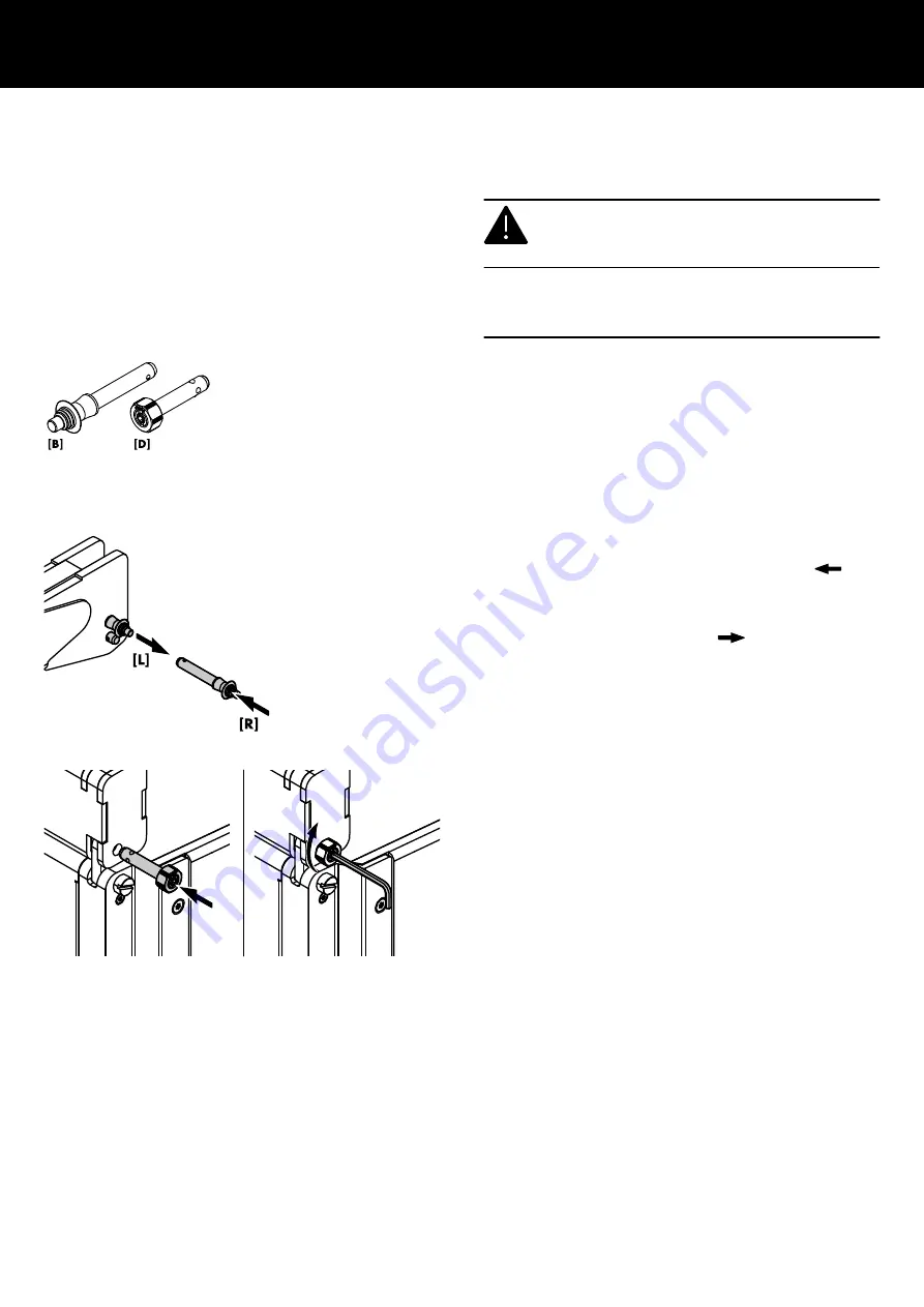
Type [B] Locking pin 10 x 45 mm used for the Mounting
adapter's Rear link slot.
Type [D] ▪ Used to fix the Front links of the first cabinet to the
Mounting frames and adapter.
▪ Used to fix the Front links of the Mounting adapter
to the bottom of the KSLi-SUB cabinet in a mixed
array configuration.
Locking pin type B - assembly
To attach a Locking pin of type B, proceed as follows:
1. Press the button to
Release the locking mechanism (
[R]).
2. Insert the Locking pin into the respective socket and link until it
is fixed in place.
3. Release the button to
Lock the pin (
[L]).
4. Recheck the Locking pin is securely locked by briefly pulling
the Locking pin towards you.
5. To release and remove the Locking pin, proceed in reverse
order.
Locking pin type D - assembly
To attach a Locking pin of type D, proceed as follows:
Tool required:
▪ Allen hex key #4 mm
1. Turn the allen hex screw (set screw) counterclockwise until the
locking balls of the pin are released.
2. Insert the Locking pin into the respective socket and link until it
is fixed in place.
3. Handtighten the allen hex screw (set screw) until the pin is
properly locked.
4. Recheck the Locking pin is securely locked by briefly pulling
the Locking pin towards you.
5. To release and remove the Locking pin, proceed in reverse
order.
d&b KSLi Rigging manual 1.1 en
12


