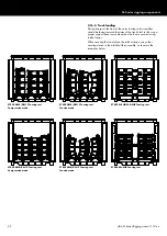
SL-Series rigging components
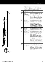
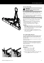
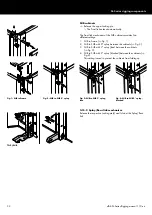
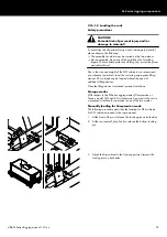
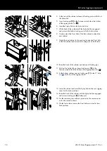
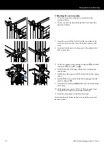
4. At the rear of the cabinet, release all Locking pins and fold out
the Splay link.
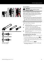
5. Insert Locking pin
[3] to the Tension mode hole at the bottom
of the rigging strand (
Þ
).
6. Insert the Splay link into the Splay link slot.
7. Lift the back of the cabinet until the Splay link has engaged
and reinsert the bottom Locking pin to fix the link in place.
8. Finally, extend the Front links of the first cabinet to attach the
next cabinet.
9. Attach the next cabinet to the previously extended Front links
of the first cabinet and reinsert its Locking pins on both sides.
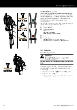
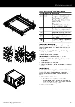
10. Raise the back of the cabinet and release all Locking pins.
11. Fold out the Splay link and insert Locking pin
[3] to the
Tension mode hole at the bottom of the rigging strand (
Þ
).
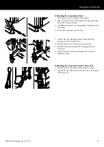
12. At the bottom cabinet, reinsert Locking pin
[1] to the 0° hole
(
Þ
) at the top of the rigging strand.
13. Lower the cabinet and insert the Splay link into the rear rigging
strand of the bottom cabinet.
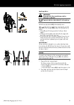
14. Raise the back of the cabinet until the Splay link has engaged
and reinsert Locking pin
[2] (Safety pin).
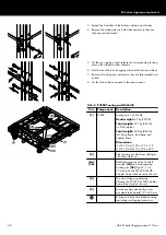
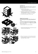
15. For the remaining two cabinets, proceed in the same manner
as for the second cabinet.
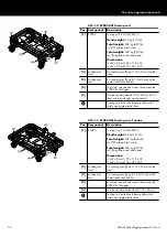
16. On the last cabinet, ensure the Front links are stored in their
Park positions.
d&b SL-Series Rigging manual 1.10 en
36

