SUB columns
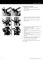
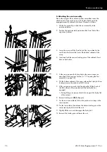
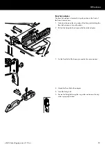
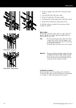
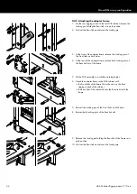
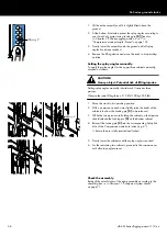
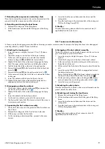
5. On the rear rigging strand, release the Locking pins of both
cabinets.
6. Fold out the Rear link of the upper cabinet.
7. Reinsert the Locking pin on the upper cabinet.
8. Fold the Rear link into the rigging strand of the bottom cabinet.
9. Reinsert the two Locking pins on the bottom cabinet.
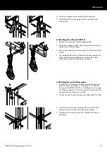
To add further cabinets, proceed in the same manner until the
assembly is completed.
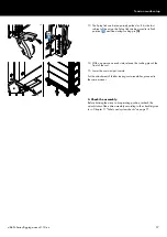
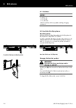
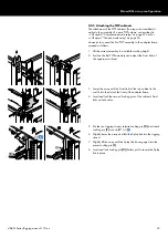
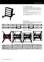
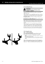
Splay option
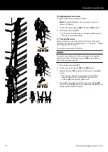
The Front links of the SUB cabinets allow for a splay angle of 2°
between adjacent SUB cabinets. Before hoisting the array, the
angle can be set in two ways:
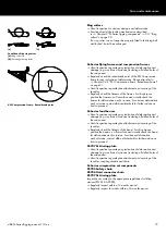
free
The second Locking pin of the cabinet's Front link is
inserted in the top hole of the front rigging strand,
as shown in the graphic opposite. This can be done
for all cabinets in one step.
The angle opens up as soon as the array is hoisted.
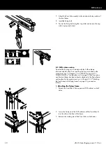
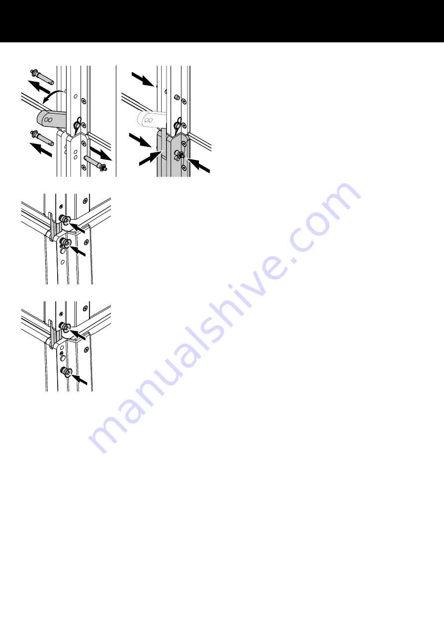
blocked The second Locking pin of each cabinet's Front link
is inserted into the second hole cabinet by cabinet
during hoisting, as shown in the graphic opposite.
Due to the design of the Front link mechanism, the
Locking pin can be inserted free of load.
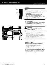
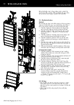
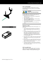
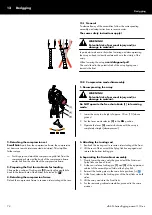
4. Check the assembly
Before hoisting the array to its operating position, recheck the
actual status of the entire assembly according to the checklist given
Chapter 11 "Safety and system checks" on page 71.
SUB to SUB, 2° splay, free
SUB to SUB, 2° splay, blocked
d&b SL-Series Rigging manual 1.10 en
62

