Derigging
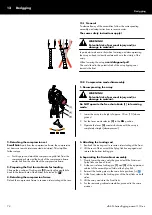
7. Detaching the compression and safety chain
Once the last assembly is stored on the cart and lowered onto the
ground, detach the compression and the safety chain.
8. Detaching and storing the load beam
1. Release the Locking pins of the flying frame.
2. Lift the load beam and reinsert the Locking pins of the flying
frame.
3. Lower the load beam and disconnect the chains and the
aiming plate.
4. Store the load beam in the dedicated slots of the touring cart
(GSL) or the flying frame (KSL).
9. Finally...
Disconnect the aiming plate and the hoist connector chain (if
applicable) from the motor hoists.
13.3 Tension mode disassembly
In Tension mode, the derigging procedure follows the setup procedure in reverse order. That means the Splay links have to be disengaged
manually cabinet by cabinet. Proceed as follows:
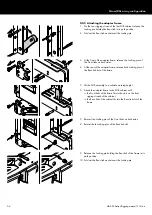
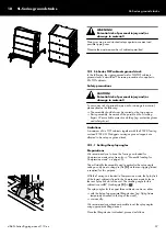
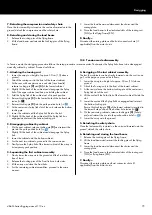
1. Attaching the touring cart
1. Lower the array to a height of approx. 30 cm (1 ft) above
ground.
2. Attach the touring cart to the front of the lowest cabinet.
3. At the rear, with one person on each side (rear handle)
release Locking pin
[2] and [3] of the lowest cabinet.
4. Slightly lift the back of the cabinet and disengage the Splay
link of the upper cabinet and keep on holding the cabinet.
5. Fold the Splay link of the cabinet out of its park position.
6. Reinsert Locking pin
[3] to the lowest hole of the bottom hole
index (
Þ
).
7. Reinsert Locking pin
[2] into the park position hole (
Þ
).
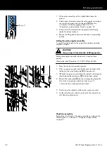
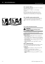
8. At the center rear Splay link slot of the cart, release the bottom
Locking pin.
9. Lower the cabinet until the Splay link fits into the slot.
10. Slightly lift the back of the cabinet until the Splay link has
engaged and reinsert the bottom Locking pin.
2. Disengaging cabinet by cabinet
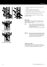
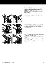
1. On the next cabinet, release Locking pin
[2] and reinsert the
pin into the park position hole (
Þ
).
2. Slightly lift the back of the cabinet and disengage the Splay
link.
3. Lower the cabinet onto the bottom cabinet.
4. For the next two cabinets, proceed in the same manner.
5. Finally store the Splay link of the lowest cabinet of the array in
its temporary park position.
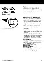
3. Separating the first cabinet assembly
1. Slowly lower the array onto the ground until the Front links are
free of load.
2. Release the Locking pins of the Front links on both sides.
3. Lift the array and store the Front links.
4. For the remaining cabinet assemblies, proceed in the same
manner.
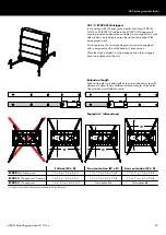
4. Derigging of the last cabinet assembly
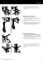
The last four cabinets can be directly lowered onto the cart in one
go. For this purpose, proceed as follows:
1. Lower the array to a height of approx. 30 cm (1 ft) above
ground.
2. Attach the Touring cart to the front of the lowest cabinet.
3. At the rear, release the bottom Locking pin at the center rear
Splay link slot of the cart.
4. Lift the cart until the Splay link of the lowest cabinet fits into the
slot.
5. Lower the cart until the Splay link has engaged and reinsert
the bottom Locking pin.
Ensure that Locking pin
[3] of the lowest cabinet is inserted to
the lowest hole position of the bottom hole index (
Þ
).
6. On the remaining cabinets, release Locking pin
[2] (Safety
pin) and reinsert the pin into the park position hole (
Þ
).
7. Lower the array onto the ground.
5. Detaching the safety chain
Once the last assembly is stored on the cart and lowered onto the
ground, detach the safety chain.
6. Detaching and storing the load beam
1. Release the Locking pins of the flying frame.
2. Lift the load beam and reinsert the Locking pins of the flying
frame.
3. Lower the load beam and disconnect the chains and the
aiming plate.
4. Store the load beam in the dedicated slots of the touring cart
(GSL) or flying frame (KSL).
7. Finally...
Disconnect the aiming plate and hoist connector chain (if
applicable) from the motor hoists.
d&b SL-Series Rigging manual 1.10 en
75

