


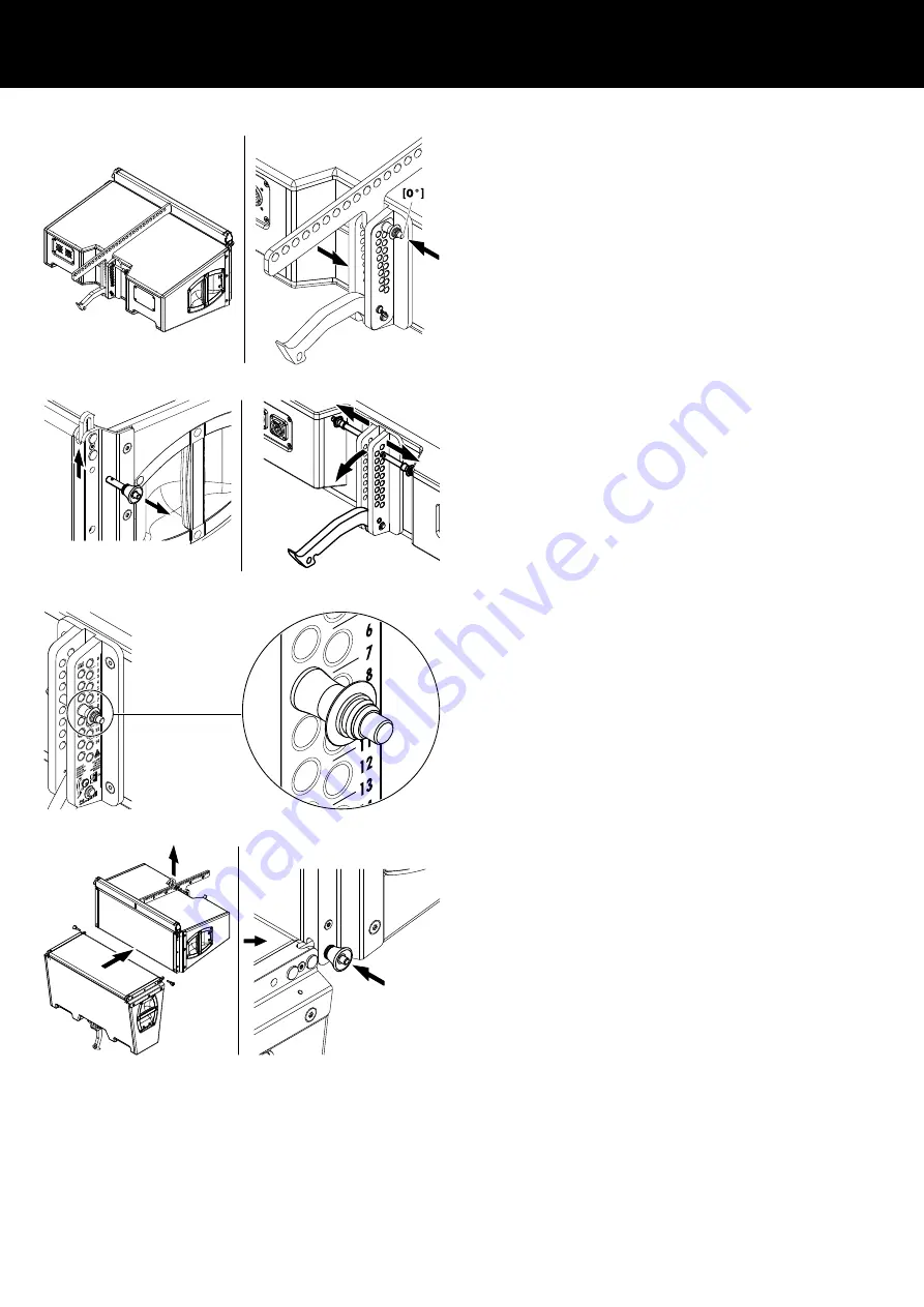
Assembly
3. On the rear align the Flying adapter with the
[0°] hole of the
rear rigging strand.
4. Insert and lock one Locking pin in the
[0°] hole.
Note: The second Locking pin is not needed and can be stored
in one of the remaining holes.
3. Prepare the next cabinet
1. Prepare the Front and Splay links of the next cabinet.
4. Preset the splay angle
The splay angles between adjacent cabinets are set at the central
rear rigging strands of the cabinets and can be set in the range
from 0° to 14° in 1° steps.
Preselect the splay angle according to your ArrayCalc simulation
and insert and lock one Locking pin in the appropriate hole.
5. Attach the next cabinet
1. Suspend the assembly according to the desired suspension
option.
2. Lift the assembly to a suitable working height.
3. Attach the prepared cabinet to the corresponding slots on the
front of the upper cabinet.
4. Insert and lock the Locking pins of the cabinet's Front links on
both sides.
d&b Z5394 Rigging manual 1.2 en
7


