D40 Touring rack assembly 10 RU - NEMA............... 5
1.1 Intended use................................................................................ 5
1.2 Scope of supply.......................................................................... 5
2
Handling, cooling and placement................................. 7
2.1 Handling...................................................................................... 7
2.2 Cooling and placement.............................................................. 7
3
Z5605.001 Mains Power Distributor and LS
Panel - NEMA........................................................................ 8
3.1 Intended use................................................................................ 8
3.2 Rear panel................................................................................... 8
3.2.1 MAINS IN............................................................................... 8
3.2.2 AMP 1 / AMP 2 / AMP 3 MAINS SUPPLY......................... 9
3.2.3 AMP 1 / AMP 2 / AMP 3 4 CH OUTPUTS......................... 9
3.3 Front panel.................................................................................. 9
3.3.1 MAINS..................................................................................... 9
3.3.2 AUXILIARY MAINS OUTPUTS 20A....................................... 9
3.3.3 AMPLIFIER MAINS OUTPUTS............................................. 10
3.3.4 4 CH OUTPUTS - NL8.......................................................... 10
3.3.5 12 CH OUTPUT.................................................................... 11
4
Z5604 I/O Panel................................................................ 12
4.1 Intended use............................................................................. 12
4.2 Overview.................................................................................. 12
4.2.1 INPUT.................................................................................... 12
4.2.2 INPUT LINK........................................................................... 12
4.2.3 Remote network option......................................................... 12
5
DN1 Ethernet switch......................................................... 13
5.1 Overview.................................................................................. 13
5.2 Mains connection..................................................................... 13
5.3 Front panel................................................................................ 13
5.3.1 ETH 9 - ETH 11..................................................................... 13
5.3.2 Mode selection..................................................................... 14
5.3.3 LED indicators........................................................................ 14
5.4 Rear panel................................................................................ 15
6
Rack wiring diagrams..................................................... 16
Contents
d&b Z5600.552 Manual 1.2 en
4
Summary of Contents for Z5600.552
Page 1: ...D Z5600 552 Manual 1 2 en ...
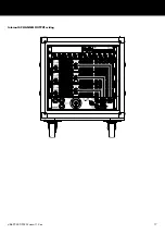
Page 17: ...Internal 4 CHANNEL OUTPUT wiring d b Z5600 552 Manual 1 2 en 17 ...
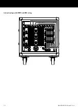
Page 18: ...Internal analog audio INPUT and LINK wiring d b Z5600 552 Manual 1 2 en 18 ...
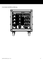
Page 19: ...Internal digital audio INPUT and LINK wiring d b Z5600 552 Manual 1 2 en 19 ...
Page 20: ...Internal Ethernet network wiring d b Z5600 552 Manual 1 2 en 20 ...
Page 21: ......
Page 22: ...D2760 US 01 06 2022 d b audiotechnik GmbH Co KG www dbaudio com ...


