5.3.2 Mode selection
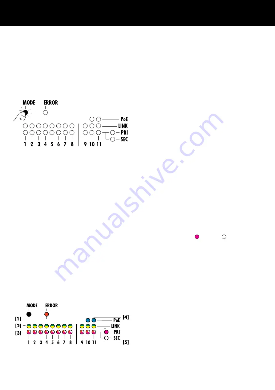
The DN1 device features a «MODE» button on the front panel.
This button is used for three different purposes:
▪
Configuration mode
Toggle between primary and secondary configurations.
▪
Reset mode
Reset the device to remote settings default.
▪
Wink mode (device indentification)
Visual identification of your device.
Configuration mode
If the DN1 device is operated within an AVB network, you must
configure all switches for use in a primary or secondary network.
The DN1 recognizes a primary or secondary connection of the
connected AVB device and indicates an error if a primary port has
been connected to a secondary switch and vice versa.
To enter the Configuration mode, proceed as follows:
1. Select and hold the «MODE» button for two seconds.
↳Either the «PRI» or the «SEC» LED starts to flash in periods
of one second with an uptime of 50%.
2. Select the «MODE» button to toggle between primary and
secondary configurations.
↳After five seconds of inactivity, the «PRI» and «SEC» LEDs
leave the Configuration mode and switch back to normal
display mode.
Note: Without an DHCP server in LinkLocal IP mode:
▪ IP adress range in primary mode:
169.254.xxx
▪ IP adress range in secondary mode:
172.31.xxx
Reset mode
The remote reset function resets all settings related to remote
communication to factory defaults. To reset the DN1 device to
defaults, proceed as follows:
1. Select and hold the «MODE» button for five seconds.
↳All AVB port status LEDs turn red for two seconds.
All other LEDs are off.
2. Release the «MODE» button.
3. Within two seconds, select the «MODE» button once again.
↳All AVB port status LEDs turn red for two seconds.
All other LEDs are off.
Alle remote settings are set to default.
Wink mode (device identification)
To activate the Wink mode, proceed as follows:
1. Select the «MODE» button once.
↳All AVB port status LEDs flash in the color of the current
Configuration mode ( = Primary / = Secondary).
2. After three seconds, the Wink mode stops automatically.
5.3.3 LED indicators
All device states and operating modes are indicated by dedicated
multi-colored LEDs.
Note: In case of an device error, connect the device to R1 via
OCA to obtain further information.
d&b Z5600.552 Manual 1.2 en
14
Summary of Contents for Z5600.552
Page 1: ...D Z5600 552 Manual 1 2 en ...
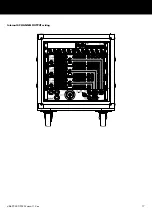
Page 17: ...Internal 4 CHANNEL OUTPUT wiring d b Z5600 552 Manual 1 2 en 17 ...
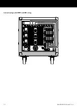
Page 18: ...Internal analog audio INPUT and LINK wiring d b Z5600 552 Manual 1 2 en 18 ...
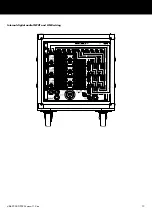
Page 19: ...Internal digital audio INPUT and LINK wiring d b Z5600 552 Manual 1 2 en 19 ...
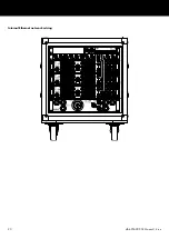
Page 20: ...Internal Ethernet network wiring d b Z5600 552 Manual 1 2 en 20 ...
Page 21: ......
Page 22: ...D2760 US 01 06 2022 d b audiotechnik GmbH Co KG www dbaudio com ...


