22
FH05B, FH18A and FH22A correspond functionally completely with the decoders described in point 5. Only features in
direct connection with the engine control are missing. This fact is marked in the setting options of the corresponding
system format. See:
- Point 7.2
- Point 8.2: CV09, CV49, CV50, CV51/Bit 0, CV56
– CV59, CV112
- Point 10.2: par017, par032, par052
– par054, par056 – par059
6.2
Installation of the locomotive function decoder
See notice in point 5.2
6.3
Connection of the locomotive function decoder
There are following variants to connect the locomotive function decoder
FH05B
:
1
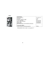
In case your locomotive is equipped with an interface according to NEM 651, use decoder FH05B-
1
. It has already
the appropriate connections for this plug. Short the ribbon cable up to approximately 5 mm and remove the rest of
the insulation. The decoder can be inserted into the interface without any problem now.
Attention
:
The additional functions AUX1 and AUX2 are issued to those interface lines at which in locomotive decoders the
motor is connected. Therefore FH05B-
1
should not be installed in a 6-pin interface of a locomotive with engine.
2
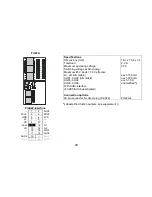
In case your locomotive has no interface socket, use decoder FH05B-
3
and wire it individually.
3
Decoder FH05B-
0
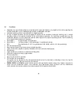
should be used only by experienced model railroaders, as the connection wires must be sol-
dered directly onto the decoder.
Summary of Contents for DH05C
Page 68: ...68 Blank page for your notes...


