background image

30


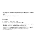
System firmat DCC


8.1 

Functions 

 
Short address 

– 127 

Long adress 

0001 

– 9999 

Speed steps 

14, 28,126 

Speed steps (internal) 

127 

Front light/rear light (dimmable) 

yes 

Additional functions (dimmable) 

Functions total 

28 

Operation with brake diodes 

yes 

Operation with brake generators 

yes 

Consist mode 

yes 

Programming on the main 

yes 

Locomotive number output 

yes 


Notice to address range: 
 

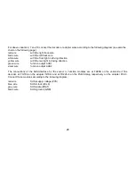
DCC-operation allows only address values from 1 to 127 for DCC-CV01, operating MM values from 1 to 255 are 
allowed. Values from 128 on lead to restricting the decoder operation only to MM, i.e. DCC-operation is no longer 
possible. DCC-"service mode" is of course still possible. 
On the other hand activating the long DCC-address by CV29/bit5 makes that operating the decoder can only be 
done  by  DCC.  Then  MM-operation  is  no  longer  possible  and  MM-programming  is  also  disabled.  Attention 
because "lock out" is possible. 


Summary of Contents for DH05C

Page 1: ...Doehler Haass Locomotive decoder User manual Locomotive decoder DH05C DH10C DH12A DH14B DH16A DH18A DH21A DH22A PD05A PD12A Locomotive function decoder FH05B FH18A FH22A...

Page 2: ...5 4 Check after installation 17 6 Locomotive function decoder FH05B FH18A FH22A 18 6 1 Functions 21 6 2 Installation of the function decoder 22 6 3 Connection of the function decoder 22 6 4 Check aft...

Page 3: ...t SelecTRIX 2 SX2 48 10 1 Functions 48 10 2 Setting options 48 10 3 Operation 58 Supplement 1 Notes to Function Mapping 59 Supplement 2 Speed characteristics 61 Supplement 3 Unamplified function outpu...

Page 4: ...youts with switching impulse is not allowed The switching impulse destroys the decoder Exception DH21A and DH22A 2 Safety instructions This product is not suitable for children under 14 years It might...

Page 5: ...upply voltage also for SUSI ZVS SUSI supply voltage ZCLK SUSI clock or AUX3 or AUX5 unamplified ZDAT SUSI data or AUX4 or AUX6 unamplified GND SUSI ground Unamplified function outputs see supplement 3...

Page 6: ...ptions Without connection wires With ribbon cable for interface per NEM651 With connection wires 12 pin connector for direct plug PluX12 13 2 x 6 8 x 1 4 0 5 A 0 5 A 18 V each 150 mA each 300 mA unamp...

Page 7: ...ng voltage LV LR dimmable AUX1 AUX2 dimmable AUX3 AUX4 With SUSI interface if AUX3 AUX4 deactivated Connection options 14 pin foil plug for direct plug mTc14 18 5 x 9 2 x 1 7 1 0 A 1 0 A 30 V each 150...

Page 8: ...LV 7 8 M1 VS 9 10 M2 Index 11 12 G1 LR 13 14 G2 15 16 AUX1 17 18 AUX2 AUX4 19 20 AUX5 AUX6 21 22 AUX7 1 22 G1 2 21 G2 3 20 GND AUX4 4 19 M1 ZCLK 5 18 M2 ZDAT 6 17 LR 7 16 VS LV 8 15 AUX1 9 14 AUX2 10...

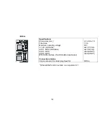
Page 9: ...plug PluX16 18 pin connection for direct plug Next18 21 pin socket board for direct plug mTc21 16 7 x 10 9 x 2 8 1 5 A 1 5 A 30 V n a each 150 mA each 300 mA je 1 0 A unamplified X DH16A 0 DH16A 2 DH...

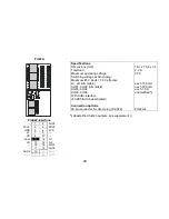
Page 10: ...e if AUX5 AUX6 deactivated Connection options 22 pin connector for direct plug PluX22 20 7 x 15 8 x 5 2 2 0 A 2 0 A 30 V each 150 mA each 300 mA each 1 0 A unamplified DH22A 4 PluX22 interface 1 2 AUX...

Page 11: ...omotive decoder PD05A is a locomotive decoder for SX1 SX2 and DCC operation There are following limitations compared to our DH decoder series No support of operating mode MM and DC analog No support o...

Page 12: ...4 PluX12 interface 1 2 3 4 5 6 LV 7 8 M1 VS 9 10 M2 Index 11 12 G1 LR 13 14 G2 15 16 AUX1 17 18 AUX2 19 20 21 22 Notice PD12A is a locomotive decoder for DCC operation only and DC analog There are fol...

Page 13: ...h 14 28 126 speed steps State of art load regulation in this way an especially smooth control mode Different control variants for an optimal adaption to the motor 127 internal speed steps Adjustable m...

Page 14: ...mode should be equipped with digital decoder New locomotives should be run in at least 30 minutes in each driving direction Before starting installation insulate the motor and all its terminals compl...

Page 15: ...4 In case your locomotive is equipped with a 14 pin interface mTc14 you should take the decoder DH14B It has already the appropriate connection for this plug The decoder can be inserted into the inter...

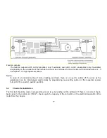
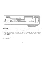
Page 16: ...on the following page red wire with the right track wire black wire with the left track wire orange wire with the motor wire which was connected to the right track wire gray wire with the motor wire...

Page 17: ...wiring of motor lighting and track there is no need to solder off the wires as the assignment can be interchanged electronically by programming see setting options of the respective system format CV51...

Page 18: ...ns Without connection wires With ribbon cable for interface per NEM651 With connection wires 13 7 x 7 8 x 1 5 0 5 A 30 V each 150 mA each 300 mA unamplified unamplified FH05B 0 FH05B 1 FH05B 3 G1 G2 T...

Page 19: ...mmable AUX3 AUX4 AUX5 AUX6 With SUSI interface if AUX3 AUX4 deactivated Connection otpions 18 pin connector for direct plug Next18 9 7 x 8 9 x 1 5 1 0 A 30 V each 150 mA each 300 mA unamplified unampl...

Page 20: ...AUX5 AUX6 deactivated Connection options 22 pin connector for direct plug PluX22 16 1 x 15 8 x 3 3 2 0 A 30 V each 150 mA each 300 mA each 1 0 A unamplified FH22A 4 Unamplified fuction outputs see su...

Page 21: ...dresses 16 additional functions DCC Short addresses 1 127 long addresses 0001 9999 with 14 28 126 speed steps 127 internal speed steps Block section operation by simple diodes in digital operation Lig...

Page 22: ...In case your locomotive is equipped with an interface according to NEM 651 use decoder FH05B 1 It has already the appropriate connections for this plug Short the ribbon cable up to approximately 5 mm...

Page 23: ...g FH18A directly into the inter face without any problem 7 In case your locomotive has no interface socket you need for FH18A either connecting adapter N18 K 3 without SUSI or N18 G 3 with SUSI for an...

Page 24: ...h the rear light in driving direction green wire function output AUX1 violet wire function output AUX2 The connections of the SUSI interface for the sound or function modules are at FH05B on the under...

Page 25: ...ia separate wires and via appropriate amplifiers Notice In case of an incorrect wiring of the light or track wire there is no need to solder off the wires as the assignement can be interchanged electr...

Page 26: ...ied by programming freely at any time Please take the programming informations out of the instructions of your programming device Instructions for Function Mapping by default see Doehler Haass website...

Page 27: ...2 Interchange track connections 4 Activation of AFB Automatic acceleration deceleration control and additional channel Function with AFB without AFB Without additional channel 1 2 With ZK without func...

Page 28: ...s overwrite the default values of the decoder In case you have varied the extended characteristic values the defaul characteristic value of the decoder must be entered again Advice for decoder DH05C D...

Page 29: ...ion to the wiring instructions for connecting the programming track Never put such a locomotive into operation 7 4 Explanation of the brake section 1 part brake section In front of the signal section...

Page 30: ...r output yes Notice to address range DCC operation allows only address values from 1 to 127 for DCC CV01 operating MM values from 1 to 255 are allowed Values from 128 on lead to restricting the decode...

Page 31: ...the decoder differ from those of the control device malfunctions may occur Please pay attention to the information concerning your digital system List of supported CV CV Name and definition Range Std...

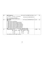
Page 32: ...eration with one additional address 3 MM operation with two additional addresses 4 MM operation with three additional addresses 5 MM operation with four additional addresses 6 MM operation with five a...

Page 33: ...he least significant byte Only if activated by CV29 0 255 192 0 255 0 19 Multiple traction address Several compound locomtives run under this address 0 deactivated Value 128 inverse direction 0 127 0...

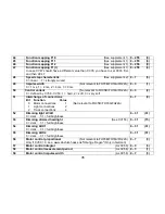
Page 34: ...llowed 8 5 Locomotive address by CV17 18 32 0 255 6 33 Function mapping F0 f See supplement 1 0 255 1 34 Function mapping F0 r See supplement 1 0 255 2 35 Function mapping F1 f r See supplement 1 If C...

Page 35: ...defined by CV56 CV59 1 hard 2 soft 3 very soft 0 3 2 51 Interchange of connections Bit Function Value 0 Motor connections 1 Not relevant to FH05B FH18A FH22A 1 Light connections 2 2 Track connections...

Page 36: ...ivated smaller 128 reduction greater 128 enhancement of the speed 0 255 0 95 Backward trim As CV66 0 255 0 105 User identification 1 0 255 0 106 User identification 2 0 255 0 112 Speed reduction analo...

Page 37: ...55 0 125 Switch off function for AUX3 Bit 0 F1 bit 7 F8 0 255 0 126 Switch off function for AUX4 Bit 0 F1 bit 7 F8 0 255 0 127 Switch off function for AUX5 Bit 0 F1 bit 7 F8 0 255 0 128 Switch off fun...

Page 38: ...Not relevant to PD05A PD12A 1 1 Switch off energy saving mode 2 2 Invert SUSI driving direction Not relevant to PD05A PD12A 4 3 Switch off SUSI starting delay Not relevant to PD05A PD12A 8 4 Activate...

Page 39: ...A PD12A Bit Function Value 6 Deactivate coupling process and timer 64 7 Coupling process only in shunting gear 128 0 255 0 144 Settings Bit Function Value 0 Dynamic channel usage BiDi 1 1 2 3 4 Immedi...

Page 40: ...re direction in shunting gear 81 Ignore driving stand in shunting gear 108 Ignore direction and driving stand in shunting gear 135 Always only one number of each definite range may be added up 0 161 0...

Page 41: ...nce CV48 0 0 deactivated If maximum speed step braking time is adjusted in seconds times 8 at smaller speed steps the decoder generates the brake ramp independently 0 255 0 155 Brake ramp backward See...

Page 42: ...2A 202 Complete table see www doehler haass de H ufige Fragen only in German 262 Version number Read only 263 Date Read only 264 Revision number Read only 265 Date Read only Notes to CV137 Activation...

Page 43: ...ogramming device indicates Error please check again the correct wiring of the locomotive and pay attention to the wiring instructions for connecting the programming track Never put such a locomotive i...

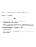
Page 44: ...eht das standardm ige Function Mapping aus Only in German Notice to address range In MM operation address values from 1 to 255 are allowed In DCC operation for DCC CV01 only values from 1 to 127 are a...

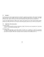
Page 45: ...s from 01 to 80 Value 0 is missing Instead of 0 always 80 must be entered Changing to programming mode The driving controller must display 0 There may not be other locomotives on the layout Notice the...

Page 46: ...tering in short mode value 07 in CV07 at first The decoder confirms changing in long mode by slow fashing of the lighting Enter now then hundredth and ten s digit of the CV which you want to change Ex...

Page 47: ...by STOP SUSI mode You gain the SUSI mode by writing value 09 in CV09 in short mode The decoder confirms that by slow flashing Enter CVs respective the related values as in long mode and reduce all CV...

Page 48: ...main yes 10 2 Setting options The features of a locomotive operated in SX2 operating mode can be varied by programming the parameters par freels at any time The programming procedure is described in t...

Page 49: ...operation additional channel 0 relative 1 Additional channel par003 par004 2 Additional channel par003 par005 1 absolute 0 1 0 008 Multiple traction address unit place Currently without function 009...

Page 50: ...1 or 2 0 1 0 022 Multiple traction mode F1 F8 Currently without function 023 Multiple traction mode FL F9 F12 Currently without function 024 Switch off function for LV Bit 0 F1 bit 7 F8 0 255 0 025 S...

Page 51: ...namic channel usage BiDi 1 1 2 3 4 Immediate starting after current interruption Special bit for lighting in analog operation Brake section output to GPIO 1 no brake section detected 0 braking Only re...

Page 52: ...f See supplement 1 0 255 1 062 Function mapping F0 r See supplement 1 0 255 2 063 Function mapping F1 f r See supplement 1 If par063 is written par075 will be set to the same value 0 255 4 064 Functi...

Page 53: ...ch off AUX4 Each 100 ms 0 deactivated 0 250 0 081 Dimming LV LR 0 dark 31 full brightness 0 31 31 082 Dimming dimmed headlight See par089 0 dark 31 full brightness 0 31 15 083 Dimming AUX1 0 dark 31 f...

Page 54: ...nt to PD05A Only valid if par088 Bit 0 1 and Bit 4 1 32 Explanations to bit 0 bit 4 and bit 5 see end of the table 0 63 0 089 Dimming mask for dimmed headlight Bit Function Value Bit Function Value 0...

Page 55: ...braking distance par051 0 0 deactivated If maximum speed step braking time is adjusted in seconds 8 times at smaller speed steps the decoder generates the brake ramp independently 0 255 0 097 Brake ra...

Page 56: ...imer for switch off AUX6 Each 100 ms 0 deactivated 0 250 0 147 Function mapping dimmed headlight Not relevant to PD05A 0 deactivated 1 28 F1 F28 29 F0 light Only valid if par088 bit 4 1 0 29 8 148 Fun...

Page 57: ...off 9 Only at F0 light on 18 Not in shunting gear 27 Only in shunting gear 54 Ignore direction in shunting gear 81 Ignore driving stand in shunting gear 108 Ignore direction and driving stand in shunt...

Page 58: ...t 4 do not care bit 5 0 Activation AUX5 AUX6 Bit 0 1 bit 4 1 bit 5 1 10 3 Operation Put the locomotive on the programming track and readout the locomotive address of the decoder par001 par002 The grou...

Page 59: ...nd switch on the outputs LV and LR LV 1 LR 2 RG 128 so you must enter the value 131 in CV38 par066 Notice AUX3 and AUX4 are not available in all decoders as amplified ones however always alternatively...

Page 60: ...ing to the waggon must be switched off but the other lights must be reversed according to the driving direction white red F0 Switches the light on white or red according to the driving direction F2 Sw...

Page 61: ...Speed step characteristic see CV48 par051 Maximum speed characteristic see CV05 par013 Speed step characteristic Linear 0 Strongly curved 7 The curvature of the speed step characteristic corresponds w...

Page 62: ...uplings Freewheeling diode Electric couplings that is couplings which can automatically uncouple remotely are magnetic articles and therefore inductive consumers When switiching off the current they m...

Page 63: ...AUX3 and AUX4 of our decoders which are designed for currents up to 1 A Hint Use the coupling functions of our decoders Timer for switching off AUX to make sure that the function output will be switch...

Page 64: ...gon train backwards to relieve the coupling Then the cou pling must be activated by relaxed towing hook Now the locomotive is driving away with activated coupling a bit until the coupling is in rest p...

Page 65: ...5 CV130 Timer for switching off AUX6 Please proceed as follows For function output AUX1 please use CV 117 par076 For function output AUX2 please use CV 118 par077 For function output AUX3 please use C...

Page 66: ...X3 CV38 Function mapping F4 in the example 32 for AUX4 Operating the couplings with 1 function key Should the couplings be connected for example to AUX3 in front and AUX4 at the rear times are to be e...

Page 67: ...the corresponding output according to the following table In case you want to activate several different functions simultanously you must add up the related values Outputs values RG AUX6 ABL AUX5 AUX4...

Page 68: ...68 Blank page for your notes...

Page 69: ...ademark of the company Doehler Haass GmbH Co KG D 81249 M nchen This product must not be disposed of with normal household waste at the end of its useful life Please use the disposal point in your mun...

Page 70: ...ny stamp DOEHLER HAASS GmbH Doehler Haass GmbH Eichelhaeherstrasse 54 Changes and errors reserved D 81249 Munich Germany Phone 49 0 89 13 93 72 21 technik doehler haass de www doehler haass de Edition...

Reviews: