


212-0024-6SS
4
July 30th, 2019
Warning
1. The use of emergency warning devices does not ensure the safety of the operator. The operator is
responsible to ensure safe operation of the vehicle regardless of whether the warning device is in
operation or not
2. The effectiveness of this or any warning device is highly dependent on proper installation and
maintenance. Read the manufactures instructions before installing and follow all recommenda-
tions.
3. When in use the operator must ensure that the warning signal is visible and not obstructed by vehi-
cle components (i.e. open trunk lid), people or other obstructions
4. This device is intended for use by authorized personnel only. It is the responsibility of the user to
ensure that all local, state, provincial and federal laws are being complied with. D&R assumes no
liability for any loss resulting from the use of this device.
5. The device must be installed so as not to reduce the output performance of vehicle systems.
6. Placement of control switches must be so as to provide convenient reach for the operator without
loosing eye contact with the road.
7. Emergency warning devices require high electrical voltages and/or currents. Properly connect and
ground all circuits. Shorting or improper grounding of this device may caused personal injuring, ve-
hicle damage and/or device damage.
8. All operators should be properly trained in the operation of this device to ensure both operator and
public safety
9. Any device used inside a vehicle, may cause severe personal injury if not properly mounted and
secured. Objects used in the vehicle may become airborne during a collision or other sudden chang-
es in vehicle speed or direction, such as braking, acceleration or turns.
10. Be sure to mount unit through the steel of the vehicle. Avoid mounting through plastic or other non
-structural materials.
11. POINT OF INSTALLATION MUST NOT INTERFERE WITH DEPLOYMENT OF VEHICLE AIR BAGS.
12. D&R Electronics recommends that this and any of our other products be installed by qualified per-
sonnel.
13. Good wiring practices and thorough knowledge of vehicle power systems is required by the installer
of this and any other product.
14. Looms, grommets, cable ties or other installation hardware should be used to anchor and protect
wiring.
15. All wire sizes must meet the minimum sizes specified by the manufacturer.
16. Splices should be minimized and made in a fashion so as to protect from moisture which could
cause corrosion thereby reducing conductivity.
17. The exact number of available connections varies by application. Refer to the specifications and
typical output fusing combinations to ensure that the safety and reliability of this product is not
compromised.
Warning
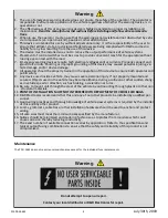
Maintenance
The PDU-16SS does not require user maintenance except for the individual fuse replacements.
Do not attempt to open or repair.
Contact your local distributor or D&R Electronics for repair.


