background image


212-0024-6SS 

July 30th, 2019


Mechanical Installation


NOTE the PDU is not weather tight.  Do not mount it in the engine compartment, on the exterior of the ve-
hicle or an area where there is moisture, dirt or other contaminants.  Ensure that the mounting location is 
flat and the device is secured to solid vehicle body parts. 

1. 

Determine an appropriate mounting location. 

2. 

Confirm there is adequate access and clearance for the wiring and all connections. 

3. 

Secure the PDU with 4 self-tapping mounting screws (not supplied). 


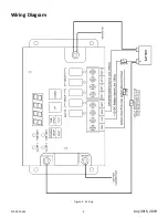
Electrical Installation


12V Battery 

Using appropriate size wire connect to the positive battery terminal fuse at the battery side with a 100A fuse 
or circuit breaker. 

Ground 

Using appropriate size wire connect to the negative battery terminal or a suitable chassis ground. 


Ignition Sense 

Connect this terminal to the vehicle ignition switch using 18 gauge wire. 


Battery Sense 

Connect this terminal directly to the positive of the battery using a 18 gauge wire fused with a 5A fuse.  This 
connection must be made in order for the PDU-6SS to work.


Ground Sense 

Connect this terminal to the negative side of the battery or a suitable chassis ground.  This connection must 
be made in order for the PDU 6SS to work.
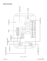


Outputs 

The PDU offers the following outputs. (1) 25A in group 1, (2) 15A in group 1, (2) 15A in group 2 and (1) direct-
ly from the battery (this output is available even when the PDU is dormant). 


NOTE:  When the IGNITION is OFF and the main +12V power input is disconnected, the DISPLAY will 
stay ON until both timers expire or the BATTERY SENSE input is disconnected. 

Summary of Contents for PDU-6SS

Page 1: ...SS Table of Contents Product Overview 2 Introduction Features Technical Specifications 3 Warnings 4 Installation 5 Wiring Diagram 6 Wire Gauge Size Tables 7 Modes of Operation 8 Programming Low Voltage Shutdown and Timed Shutdown 9 Package Contents 10 Warranty and Product Return Policy 12 ...

Page 2: ...212 0024 6SS 2 July 30th 2019 Product Overview Figure 1 PDU 6SS ...

Page 3: ... Shutdown 2 minutes TO 30 hours Vehicle Battery Voltage Monitoring Each output has an LED fuse status indicator ZERO Current consumption in Standby Mode Timed Shutdown Mode Test Mode all outputs ON for 20 seconds Reset Mode resets all outputs to zero 6 Outputs 1 battery and 5 timed Technical Specifications Voltage Range 11 18 VDC Maximum Current Load 15A per output fused at 20A 25A per heavy duty ...

Page 4: ...hould be properly trained in the operation of this device to ensure both operator and public safety 9 Any device used inside a vehicle may cause severe personal injury if not properly mounted and secured Objects used in the vehicle may become airborne during a collision or other sudden chang es in vehicle speed or direction such as braking acceleration or turns 10 Be sure to mount unit through the...

Page 5: ...ound Using appropriate size wire connect to the negative battery terminal or a suitable chassis ground Ignition Sense Connect this terminal to the vehicle ignition switch using 18 gauge wire Battery Sense Connect this terminal directly to the positive of the battery using a 18 gauge wire fused with a 5A fuse This connection must be made in order for the PDU 6SS to work Ground Sense Connect this te...

Page 6: ...212 0024 6SS 6 July 30th 2019 Figure 2 Wiring Wiring Diagram ...

Page 7: ...ngth 3 drop 5 ft 5 10 ft 10 15 ft 15 20 ft 25 30 ft 25 10 6 6 4 2 50 6 4 2 2 0 75 6 2 1 0 3 0 100 4 2 0 2 0 4 0 Table 2 Recommended Circuit Load Wire Size Max Total Load Current Amps Wire Size AWG vs Wire Length 3 drop 1 5 ft 5 10 ft 10 15 ft 15 20 ft 25 30 ft 5 18 18 18 16 14 10 18 16 14 14 12 15 18 14 12 12 10 20 16 14 12 10 8 ...

Page 8: ...voltage reaches a pre set value This setting is the same for both groups Timed Shutdown Mode The PDU allows the user to set the time remaining after the ignition switch is turned off This setting is the same for both groups The 7 segment display will cycle through and indicate the time remaining for each output group Test Mode Pressing the TIME SETUP TEST button for at least 2 seconds will start a...

Page 9: ...ET button again to save the new values Note When the vehicle battery voltage drops below the pre set voltage the outputs will turn off This is the same for both groups The minimum shutdown voltage cannot be set below 11 5VDC unless the vehicle is being fitted with a second battery Timed Shutdown Setup The PDU 6SS factory default shutdown times are set to 2 minutes for GROUP 1 outputs 2 hours for G...

Page 10: ... 16 out display dual programmable timer and voltage 1 212 0024 6SS Manual PDU 6SS unit 1 Designator sheet for PDU 6SS to record all setup installation data 4 196 0070 Lug LD 6 AWG stud 1 4 16 205 0052 Spade 8 16 14 Ga Package Contents NOTE MINI and MAXI fuses are available for purchase ...

Page 11: ...212 0024 6SS 11 July 30th 2019 NOTES ...

Page 12: ...or removal or installation Lamps flash tubes batteries or other items considered consumables are not covered under warranty This warranty is in lieu of all other express warranties D R Electronics makes no warranties ex pressed or implied other than the express warranties contained herein WARRANTY PRODUCT RETURN POLICY In order to provide you with faster service product returns for repair or repla...

Reviews: