PART#: 212-2014-K
6
July 30th, 2019
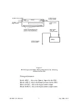
1. Run a 6 AWG wire lead from the Battery via a fusible link or circuit breaker rated at
80A to the PDU14.
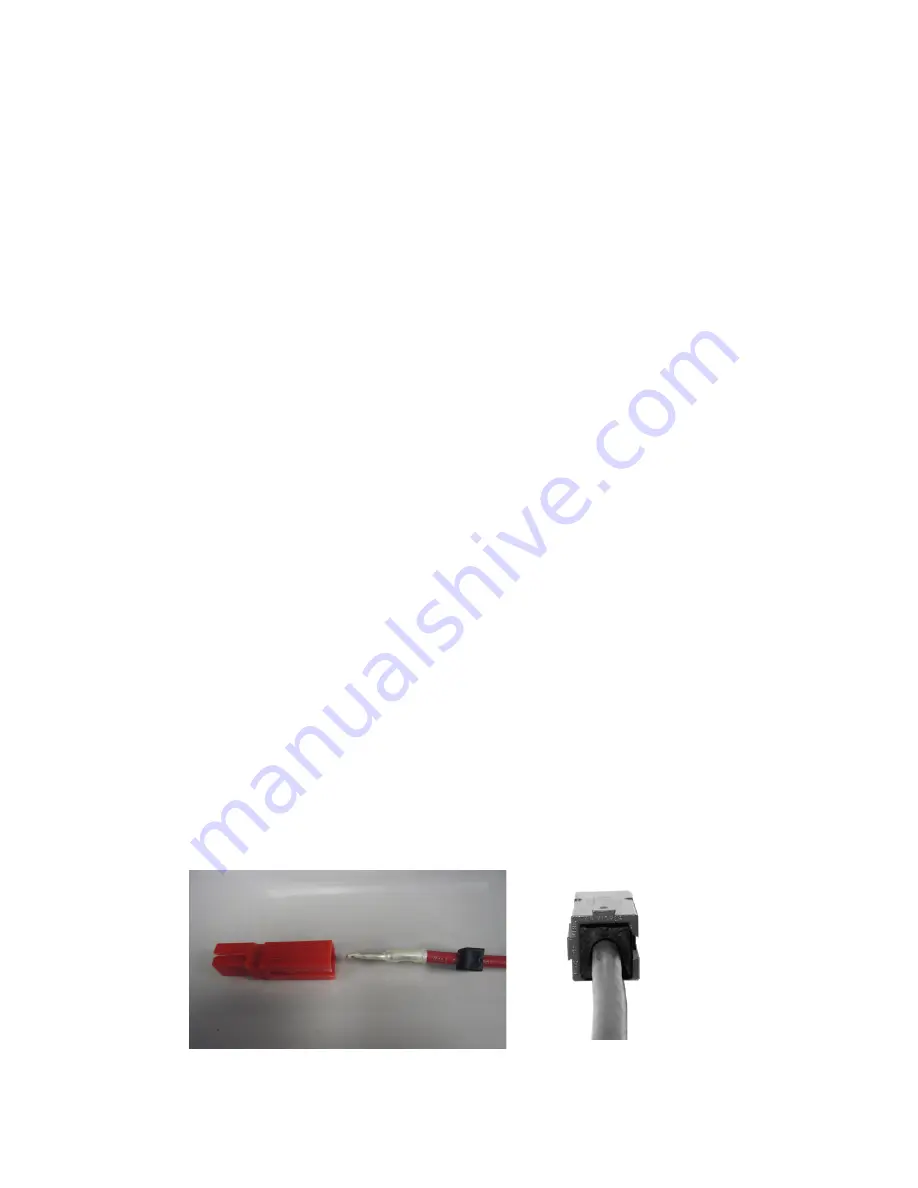
2. Cut to length and slide one of the provided grommets over the wire (Figure 3.)
3. Strip 1/2” length of insulation from the end of the wire, insert the bare wire into the pin
connector , crimp or solder.
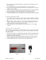
4. Insert pin and wire into the Red connector housing until it “snaps” into place, pay atten-
tion to the orientation of the pin when inserting it into the housing see Figure 3.
5. Slide the grommet down the wire into the plug to seal connection (Figure 4).
6. Connect the Red plug on to the battery input “+12V IN” power claw clip of the PDU14.
Connecting ground input to the PDU
1. Run a 6 AWG wire lead to the chassis of the vehicle, if necessary run this wire directly
to the battery negative terminal if a good low resistance chassis connection is not availa-
ble
2. Prepare and the 6 AWG Ground wire for connection to the PDU using the same proce-
dure as the battery input wire (Figures 3 & 4) and insert the finished pin, wire, and
grommet combination into he remaining black housing.
3. Connect the plug to the “GND” Input power claw clip next to the “+12V IN” plug
(Figure 3).
Conn12V OUT from the PDU
The
PDU
supplies a single high current output which may be used to power a high current
device such as a light-bar, this output uses the same style of power connector as the input
wire from the battery:
1. Run the wire from device (i.e. light and siren controller) to the
PDU
mounting location.
Using the same process for the Battery input wire (steps 2 and 3) prepare the wire for
insertion into the BLUE pin housing.
2. Insert the wire and pin combination into the Blue housing until it “snaps” into place,
slide the grommet down the wire into the plug to seal connection (Figures 3 & 4).
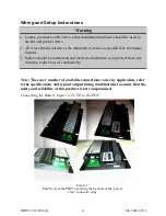
3. Connect the Blue plug onto “+12V OUT” power claw clip (Figure 1).
Figure 4
Figure 3


