PART#: 212-2014-K
7
July 30th, 2019
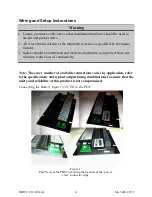
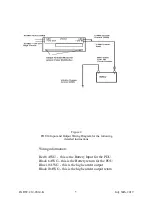
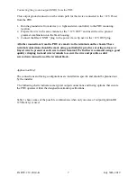
Connecting the ground output (GND) from the PDU
This output ground connection is the return path for the device connected to the +12V Power
from the PDU.
1. Run the ground wire from device (i.e. light and siren controller) to the PDU mounting
location.
2. Prepare the wire in the same manner as the “+12V OUT” and insert the wire, pin and
grommet combination into the black housing.
3. Connect the Black “GND” plug to the power claw clip next to the +12V OUT plug.
All other connections from the PDU are made via the terminals on the chassis. These
terminal connections should be made using good industry practice ensuring no loose or
frayed wire be present at each screw-down terminal. We further recommend using a good
quality crimping tool and wire terminals to secure the wire and provide a solid
screw-down connection at the terminal block.
Application Brief
The connections and fusing configurations are installation specific and should be planned out
by the installer.
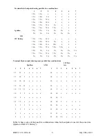
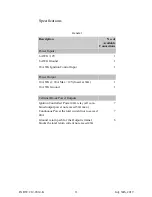
The following charts indicate some typical output connections and fusing options, that ensure
the PDU operates within the designed maximum specifications.
Table 1 shows some of the possible combinations when only one area of output (Ignition OR
12V Battery) is used.


