Part NO: 212-0024-8S
10 July 30th, 2019
Connecting the power output from the PDU
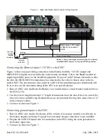
Determine the type of power required by the connecting equipment (i.e. ignition controlled,
constant/battery or timed) and start connecting the vehicle equipment according to the system
design requirements.
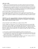
1. All power connections will terminate at the
PDU
, bring the POWER and GROUND
(return) wires for the equipment to be connected directly to the
PDU
.
2. Connect the power wire from the equipment to the appropriate output on the
PDU
(i.e. ig-
nition controlled, constant/battery or timed).
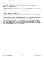
3. Connect the return wire from the equipment to one of the terminals screws on the
GROUND terminal block or any chassis GROUND.
As you install the equipment distribute the many ground return wires to be connected
to terminal block evenly over the entire group of 7 terminal screws.
It is highly recommended that connecting wires to the screw terminals on the
GROUND terminal block be terminated with spade/fork terminals to make neat relia-
ble connections.
1. Once all the wire connections to and from the
PDU
are completed the output fuses can be
installed according to the required rating of the connected equipment.
The
PDU
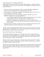
accepts a standard Automotive Blade ATO/ATC Type fuses, each fuse location has
an LED indicator to show that the fuse is in place and working. The LED indicator will glow
RED if the fuse is “GOOD” otherwise it will be off.
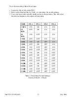
Setting The Time Delay on Timed Outputs
The time delay for the timed outputs is user selectable and is set by a 4 position miniature
switch that is accessible through the cover at the back of the
PDU
. The delay time can range
from 2 minutes to 13 hours, this function is triggered by turning the vehicle ignition “OFF”
and only if the battery voltage is lower than 14V.
When the selected time has elapsed power to all timed outputs will be shut “OFF”. If during
the timing cycle the ignition is turned back on the timer will reset and the time cycle will re-
start when the ignition is turned off again.
The
PDU
has a built in Voltage Monitoring circuit, this will automatically shut down any timed
outputs if the battery voltage is reaching a “CRITICAL LOW” point (11.5 VDC). Similarly
this Voltage monitor circuit will cut off power to the timed outputs if the battery voltage ex-
ceeds 18V DC.


