

Part NO: 212-0024-8S
14 July 30th, 2019
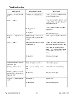
Troubleshooting
PROBLEM
POSSIBLE CAUSE
SOLUTION
No power at any of the out-
puts
No relay “click”
No power to “
12V INPUT”
Faulty ground
Faulty Unit
Check 12V INPUT connection for
loose or missing wires.
Check Battery fusible link or circuit
breaker, if this is faulty replace it if
it is tripped reset it.
Check Vehicle Chassis “Ground”
connection
Return Unit for repair
No power to “Ignition” cir-
cuits
No relay “click”
Ignition trigger wire not con-
nected to PDU “ignition” ter-
minal
Incorrect connection to vehicle
wiring harness
Faulty Unit
Verify “ignition” input connection
Consult the factory specifications
and wiring diagrams for the vehicle
Verify that the ignition wire re-
12V when vehicle ignition
is set to “ON” and vehicle is run-
ning.
Return unit for repair
Timed outputs not on while
ignition is “ON”
Timing cycle incorrect
Timing cycle does not end/
start and all ignition control
function “OK”
Linked to ignition control.
Timing switch settings incor-
rect
Faulty unit
Follow above process
Set switches for desired timing
Return unit for repair
No power to Individual Cir-
cuits
Fuse Blown
Faulty Circuit
Replace fuse
Return Unit for repair


