


Part NO: 212-0024-8S
2 July 30th, 2019
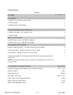
Applicable Models
PDU42-8S
Introduction
The
Power Distribution Unit (PDU)
is a compact and convenient point of load power dis-
tribution product for installed electrical devices. By using this device and carefully plan-
ning the distribution of mobile equipment power feeds, complex independent wire runs
and unreliable fuse panel connections can be avoided.
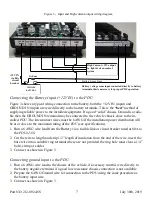
The
PDU42-8S
is directly connected to the vehicle battery and ground, thus providing a
direct easily traceable route to the input power source avoiding interfering with the vehi-
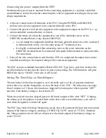
cles factory wiring harness. The specifics for safely connecting the
PDU42-8S
to a vehi-
cles electrical system are outlined in the detailed instructions to follow.
Each circuit can be individually fused further reducing risk of damage to devices from
circuit overload. Each fused output has a red LED to indicate when a circuit fuse is
GOOD.
The
PDU42-8S
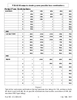
unit provides two 50A high current outputs and up to 24 additional out-
puts divided into “constant/battery”, “ignition controlled” and “timed” outputs to meet
the typical in-vehicle equipment installation requirements. These output features have
the following characteristics;
1) Constant/Battery Outputs:
There are 8 output connections each with individual fuses, that are on at all time
providing the
PDU
is connected to the battery.
2) Ignition Controlled Outputs:
The 8 output power connections, also individually fused p12V output
while the vehicle ignition is ON. Power will be immediately turned OFF at these
outputs when the vehicle is shut down and the ignition key removed (some vehi-
cles still maintain and “ignition ON” signal when the key is still in the ignition
switch) careful selection of the proper ignition control wire can help avoid this sit-
uation..
3) Timed Outputs:
There are 8 output power connections fit with individual fuses. These outputs are
ON while the ignition control signal is applied to the PDU, and will go through a
pre-set timed off sequence once the ignition is turned OFF. The time to OFF is us-
er selectable and is selected by the installer based on the system design.
The timed off sequence is also controlled by an onboard battery voltage monitor. If
the battery voltage becomes too low the timing sequence is interrupted and a shut
down of the timed outputs will begin. This feature prevents a total discharge of the
vehicle battery while the ignition is OFF and the equipment is in use.


