


Part NO: 212-0024-8S 5 July 30th, 2019
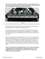
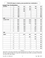
Note: The exact number of available connections varies by application, refer
to the specifications and typical output fusing combinations to ensure that the
safety and reliability of this product is not compromised.
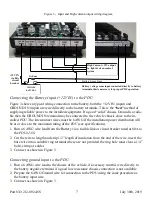
Figure 1
Left side view of the PDU42-8S showing the location of the high power Input and Output connectors.
The wiring to the PDU will be determined by the installers design of the power
distribution and wire routing for the installed equipment.
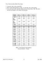
Fuses and wire for the screw terminal outputs are selected based on equipment
power requirements and their manufacturers recommendations. The maximum
fuse sizes and some possible combinations are shown in a table on the following
page Figure 2.
The fuses are indicated as 20A maximum, the x is no fuse or no connection and
the N/A means that the limit of that area has been reached with the indicated max-
imum fuse values and that spot is not available. Many combinations can be de-
rived based on the
PDU
specifications and the equipment power requirements.
The table in Figure 2 shows eight of these possible combinations, these can be
used as a starting point to help plan the power distribution for the intended appli-
cation.
NOTE: Interconnect Wire, Mounting Hardware, Fuses and any termination
or additional hardware mentioned in the installation procedure IS NOT
SUPPLIED. These items are industry standard and are provided by the
installer at the time of installation.


