Part NO: 212-0024-8S 7 July 30th, 2019
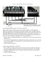
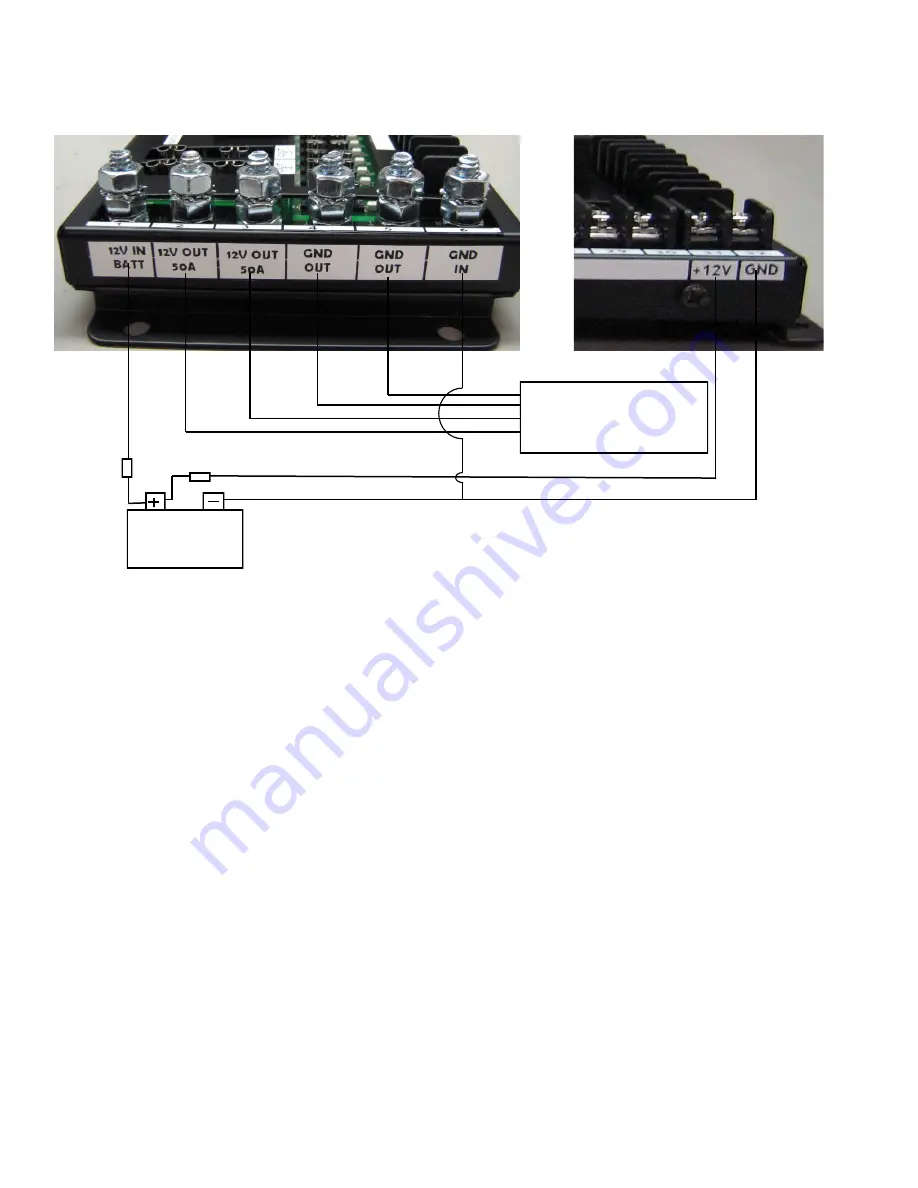
Figure 3 - Input and High current output wiring diagram
Connecting the Battery Input (+12V IN) to the PDU
Figure 3 shows a typical wiring connection to the battery, both the +12V IN (input) and
GROUND IN (input) are wired directly to the battery terminals. This is the
“best”
method of
supplying reliable power to the installed equipment. If a good “solid” chassis Ground is availa-
ble then the GROUND IN terminal may be connected to the vehicle chassis close to the in-
stalled
PDU
. The interconnect wires must be 6 AWG if the installation power distribution will
be at or close to the maximum rating of the
PDU
(see specifications).
1. Run a 6 AWG wire lead from the Battery via a fusible link or circuit breaker rated at 80A to
the
PDU42-8S
.
2. Cut the wire to length and strip 1/2” length of insulation from the end of the wire, insert the
bare wire into a suitable ring terminal (these are not provided the ring hole must clear a 1/4”
bolt), crimp or solder..
3. Connect as shown in Figure 3.
Connecting ground input to the PDU
1. Run a 6 AWG wire lead to the chassis of the vehicle, if necessary run this wire directly to
the battery negative terminal if a good low resistance chassis connection is not available
2. Prepare the 6 AWG Ground wire for connection to the PDU using the same procedure as
the battery input wire.
3. Connect as shown in Figure 3.
+12V IN
via 80A
circuit
breaker
VEHICLE
BATTERY
High C12V output
i.e. light & siren control
system
Battery voltage sense input connected directly to battery
terminals, this is necessary for proper PDU operation.
1A Fuse
Battery Sense Lines


