Part NO: 212-0024WB
12
July 30th, 2019
Timed Modes of Operation
Battery Voltage:
A)
Between 14.0 to 18V
the output of the “PDU Timer ” will be
ON unconditionally
.
B) If the battery voltage drops
below 14.0V
and the
ignition is OFF
, the “PDU Timer” will
commence a predetermined countdown delay at the end of which the unit will shut-off and
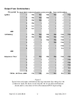
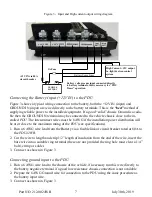
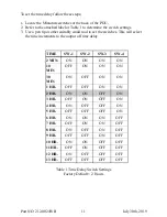
go into “STANDBY” mode. This delay is set by the 4 DIP switches on the “PDU Timer” ,
THE FACTORY DEFAULT IS TYPICALLY SET TO 2 hours (DIP switch 3 =OFF all
others on). Check and set this accordingly.
C) If the battery voltage recovers and is raised above 14.0V (i.e.. the battery is being charged)
the countdown process will cease and the “PDU Timer” will go into “ON” mode
Ignition:
A) If the ignition switch is OFF and the unit is in countdown mode, cycling the ignition switch
ON/OFF will reset the countdown. Always at the end of the countdown the “PDU Timer”
will be in “STANDBY” mode.
B) The ignition switch “ON” will always reset the countdown and prevent it from timing down
(override countdown mode and keep the “PDU Timer” ON).
Override:
The override circuit can be triggered by the PB (push button) momentary on switch on the
“PDU Timer” . Triggering the override will send the unit into “ON” mode for “2” minutes re-
gardless of the operating mode, or battery voltage (providing battery is not completely dead
and the ignition is off).
Standby:
Once the “PDU Timer” is in STANDBY mode, the only way for the system to come out of
STANDBY is;
A) Override Switch is pressed
B) Battery is charging and the battery voltage is over 14V.
C) Ignition switch is switched ON.
LED Indicator:
The LED indicator shows the mode or status by the following indications;
A)
STANDBY
– LED blinking at the rate of
10% ON 90% OFF
.
B)
ON
- LED
ON solid
C)
COUNTDOWN
- LED blinking at the rate of
90% ON 10% OFF


