
Part NO: 212-0024WB
13
July 30th, 2019
Warning
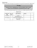
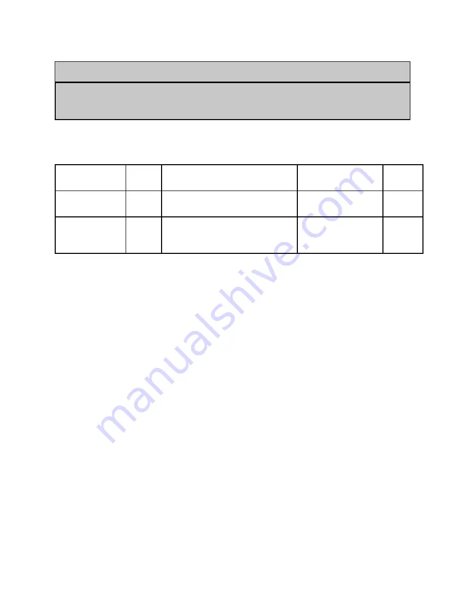
Maintenance
The
PDU42WB
does not require user maintenance except for the individual fuse replacement.
There are no user maintained parts. Do not attempt to open or repair.
Contact your local distributor or D&R Electronics for repair.
The following replacement parts and accessories are available for the PDU 42WB
.
PARTS LIST
PART NUM-
BER
QUAN-
TITY
DESCRIPTION
NOTES
PDU42WB
1
POWER
DISTRIBUTION UNIT
212-0024WB
1
PDU 42WB OPERATION / IN-
STALLATION
MANUAL