Part NO: 212-0024WB
8
July 30th, 2019
SPECIAL NOTES:
1. Making a good solid ground connection to the chassis requires the removal of the paint
right down to the shiny bare metal at the point of securing the ground wire to the chassis.
2. All ground returns for equipment connected to the
PDU
should terminate at the
PDU
using
the GROUND terminal block. To minimize wire bunching and exceeding the current capac-
ity of each screw terminal on the output block (15A max per screw connection) distribute
these return wires evenly across the whole GROUND block.
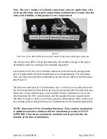
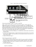
Connecting the Battery Voltage Monitor from the PDU
We recommend using 18 AWG stranded wire for this connection. The color for the wires
should be RED and BLACK, however if this is not available then two distinct colors should be
used. It is very important to maintain the correct polarity from the battery to the PDU sense in-
puts.
WARNING: Any wire connected directly to the battery should be fused, and located as
close as possible to the POSITIVE battery terminal. We recommend a 1A fuse inside an
inline weather resistant fuse-holder be used.
Connecting high Current (AMP) power output from the PDU
The
PDU
supplies a single high current (+12V OUT) output which may be used to power a
high current device such as a light-bar, this output uses the same style of power connector as
the input wire from the battery (Figure 1). Connection to these outputs are via 8 AWG power
wires terminated with a ring terminal. This output is rated at 30A DC continuous current and
fused by a 50A MAXI fuse (MAX50 or AMT50 are the part numbers for this fuse).
1. Leave the fuse out until the attached equipment is properly wired and secured.
2. If a single connection (one power and one ground) is to carry the full current then the wires
must be 8AWG in size. Otherwise the wire supplied by the manufacturer for the equipment
will be used to connect to these output power clips.
3. Run the wire from device (i.e. light and siren controller) to the
PDU
mounting location. Us-
ing the same process for the Battery input wire (steps 2 and 3).


