background image

July 31, 2019             

                                                10                                           Part#: 212-0042 


Programming Inter Clear or Radio Rebroadcasting


1)  Enter setup mode Enter by holding SW6+SW7 and wait for the 2 beeps 


2) Set 

SW11 ON for Inter Clear 

or 

SW11 OFF for Radio rebroadcast

. Save the configuration, press and 

hold SW9 (STBY/PA) until the long beep, this confirms the program is saved. 
 

Factory Default Reset 

 
The keypad setup can be reset to the factory default by following these steps: 
 

- disconnecting the keypad data pigtail from the extension data cable; 


- press and hold down the STBY/PA switch 


- reconnect the keypad data pigtail to the extension cable and release the STBY/PA switch after 


the unit makes a long beep (aprox. 2 sec.)  

The system is reset to factory default. 

Figure 6- Programming RADIO-rebroadcasting 

RDS17S  PUSH BUTTON LABEL INSTALLATION INSTRUCTION 

- Remove the Slide Switch red knob. 
- Depress the locking tab on each end 
to separate the front and back covers. 
- Slowly remove the front cover and 
change the push button labels. 
- Assemble the front and rear covers 
and make sure that the side tabs are 
locked. 
 - Install the Slide Switch knob. 

Summary of Contents for RDS17S

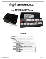
Page 1: ...g 3 Wiring 3 Operating Instructions 6 Standard Features 6 Operation 6 Programming 7 RDS Push Button Label Installation Instruction 11 Vehicle Boosting 12 RDS Packing Lists 13 Service and Maintenance 14 Troubleshooting 14 Specifications 15 MANUAL RDS17S LIGHT AND SIREN CONTROL SYSTEM Model RDS17S ...

Page 2: ...2 0042 Installation Safety Installer Qualifications For proper installation of this product you must have a good understanding of automotive electr vehicle sound lighting and warning equipment Figure 1 RDS 17S Wiring Diagram ...

Page 3: ...Part 212 0042 3 July 31 2019 ...

Page 4: ...this mode the jumper on J5 must be removed P KILL Park Kill input is 12VDC or GROUND activated and used to immediately disable all siren tones when a vehicle is shifted into park Connect the P KILL pin to the vehicle transmission neutral safety switch signal wire This wire should output a signal when the vehicle is shifted into park Output 10 11 HLF 12V outputs the outputs from these terminals can...

Page 5: ...to flash One output can be made to function as momentary 9 SEC timer or 30 SEC timer button if necessary Siren Tones Three siren tones are standard WAIL SW11 YELP SW12 and STINGER SW13 si ren tones are activated by pressing the appropriate touch button on the touchpad Air Horn MANUAL SW14 The electronic air horn can be sounded by pressing this button This function overrides other siren tones and t...

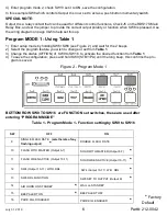
Page 6: ... 3 Change the status OFF ON of SW9 to SW16 to activate the desired function from Table 1 4 To save the configuration press and hold SW9 STBY PA until the long beep this confirms the pro gram is saved Figure 2 Program Mode 1 Factory Default Table 1 Program Mode 1 Function setting by SW9 to SW16 BOTTOM ROW SW9 TO SW16 are FUNCTION set switches these are used after entering PROGRAM MODE 4 Enter progr...

Page 7: ...ORN SW14 MANUAL 10 DO NOT CHANGE 11 ARROWSTICK ENABLED and controlled by SW16 ARROWSTICK DISABLED 12 STANDARD ARROW CTRL CODE 3 911 ARROW CONTROL 13 SW8 SOLID SW8 MOMENTARY 14 SW15 Output 12 ACTIVE W O IGNITION SW15 Output 12 ACTIVE W I INGITION 15 SEE TABLE 3 16 SEE TABLE 3 Figure 3 Program Mode 2 Table 2 Program Mode 2 Function setting by SW9 to SW16 SETTING SW15 SW16 OUTPUT 4 TIMER FUNCTION 1 O...

Page 8: ...ding SW4 SW8 and wait for the 2 beeps 2 Select which switches will be ON with Master 3 Save the configuration press and hold SW9 STBY PA until the long beep this confirms the program is saved SLIDE 3 1 Enter setup mode Enter by holding SW5 SW8 and wait for the 2 beeps 2 Select which switches will be ON with Master 3 Save the configuration press and hold SW9 STBY PA until the long beep this confirm...

Page 9: ...wstick Modes When ARROWSTICK is enabled the RDS17S has two modes of arrowstick control CODE3 system default this mode it is a data control only arrowstick and it needs a D R traffic director or a D R digital to analog convertor box in order to control standard ground controlled traffic direc tors Using SW16 the following patterns can be activated LEFT ARROW RIGHT ARROW CENTER OUT CENTER FLASH ALTE...

Page 10: ...e keypad data pigtail from the extension data cable press and hold down the STBY PA switch reconnect the keypad data pigtail to the extension cable and release the STBY PA switch after the unit makes a long beep aprox 2 sec The system is reset to factory default Figure 6 Programming RADIO rebroadcasting RDS17S PUSH BUTTON LABEL INSTALLATION INSTRUCTION Remove the Slide Switch red knob Depress the ...

Page 11: ...NTRELEC 1 PA MIC MICROPHONE W JACK PLUG 1 CA 0113 MICROPHONE CLIP HEAVYDUTY 1 215 0151 MICROPHONE CABLE 18 ft 1 215 0016 DATA CABLE 1 200 0139 DATA CABLE COUPLING BOX 1 401 0009 SCREW 10 32 X 3 8 4 401 0007 WASHER 10 ZINC 4 401 0010 LOCK WASHER 10 ZINC 4 811 0037A SIREN MOUNTING BRACKET 1 RDS17S RDS17S SYSTEM 1 212 0042 RDS17S INSTALLATION MANUAL 1 216 0014 TOUCHPAD LABEL SHEET 1 211 0008 PACKING ...

Page 12: ...e gauge are used for the system s power and ground lines Siren s tone changes when another light or heavy load comes on The electronics may not be operating properly Ensure that all screws of terminal blocks are tight While using the two way radio lights come on or function s is are unstable Loose or poor ground connec tion or improper power wiring Use dedicated power and ground wires from battery...

Page 13: ...ions Height 2 45 Width 6 66 Depth 6 44 Depth with touchpad 7 42 Siren Operating Current 10 Amps Frequency Range 734 to 1311 Hz nominal Cycle Rate Wail 20 cycles min Yelp 200 cycles min Stinger 800 cycles min Nominal Voltage Output 48V p p 11Ω load Audio Frequency Response 100 4000 Hz 3dB Audio Distortion 10 or less Audio Power 32 watt Input Impedance 600Ω radio TOTAL current draw not to exceed 60A...

Page 14: ...July 31 2019 14 Part 212 0042 NOTES ...

Page 15: ...Part 212 0042 15 July 31 2019 ...

Page 16: ...for removal or installation Lamps flash tubes batteries or other items considered consumables are not covered under warranty This warranty is in lieu of all other express warranties D R Electronics makes no warranties expressed or implied other than the express warranties contained herein WARRANTY PRODUCT RETURN POLICY In order to provide you with faster service product returns for repair or repla...

Reviews: