July 31, 2019
6 Part#: 212-0042
SW
OFF
ON
9
SINGLE FLASH RATE
(sets the rate of any
flashing output)
*
DOUBLE FLASH RATE
10
FLASH WITH MASTER (Output 6-7)
SOLID WITH MASTER (Output 6-7)
*
11
FLASH WHEN ACTIVE (Output 10-11) SOLID WHEN ACTIVE (Output 10-11)
*
12
SW4 (Output 10-11) WITH DRL
SW4 (Output 10-11) W/O DRL
*
13
SW8 DRL FUNCTION
SW8 SET TO OUTPUT (Output 9)
*
14
AIR HORN ON STANDBY
*
WAIL on STANDBY
15
BEEP ALERT ON
*
BEEP ALERT OFF
16
PARK KILL DISABLED
PARK KILL ENABLED
*
Program MODE 1 - Using Table 1
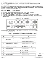
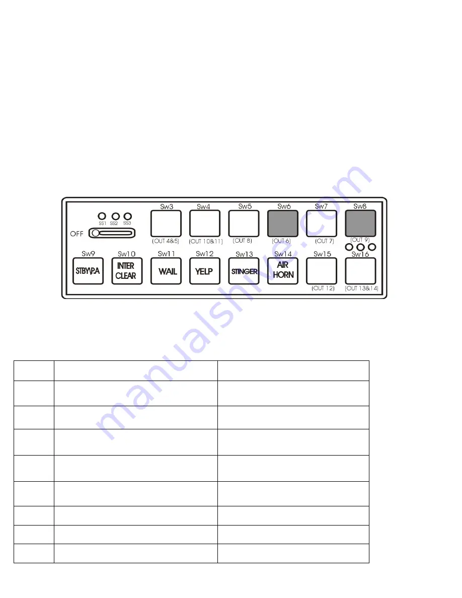
1) Enter setup mode by holding SW6+SW8 (see Figure 2 ) and wait for the 2 beeps.
2) Select the program feature you wish to change or set from
Table 1
.
3) Change the status (OFF/ON) of SW9 to SW16 to activate the desired function from
Table 1
.
4) To save the configuration; press and hold SW9 (STBY/PA) until the long beep, this confirms the pro-
gram is saved.
Figure 2 - Program Mode 1
*
Factory
Default
Table 1 - Program Mode 1 - Function setting by SW9 to SW16
BOTTOM ROW SW9 TO SW16 are FUNCTION set switches, these are used after
entering “PROGRAM MODE”
4) Enter program mode 2, check SW13 set it to ON, save the configuration.
In this example SW8 which controls Output 9 is now set to act as a push button momentary switch.
SPECIAL NOTE:
Output 9 is a relay contact that can be used for different control functions, Check J5 on the RDS17S Main
Relay Box, and set the jumper to provide the correct output polarity or function when SW8 is pressed. Use
the wiring diagram on page 4&5 to help set this up.

