AIRMATE-USB manual page: 15
6.
SETTING UP ROUTINES MODULE 1-4
-
Connect a power-amp, recorder or transmitter to the left/right outputs.
- Connect a high impedance headphone to the "phones"-jacks on the front.
- Connect the microphones as described.
- Act like wise with turntables, CD players and jingle machines.
- You can eventually connect a D&R Telephone Hybrid to the Clean feed output.
- Be sure that Jumper J7 is on position 3-4 to avoid feedback when returning the Telephone
Hybrid output on these channels.
- Connect a red light indicator when there is a need for it.
- The Announcer output can feed a high impedance headphone directly.
- Now that everything is connected, follow the adjustment procedure.
Note; for mikes, only activate the grey Mic switch, for line level leaves this switch up and select line A or B
- Put on your headphones and turn the headphone-volume control to "12 o'clock" position.
- Turn all the gain-controls and the master-control to the left.
- Set all equalizer-controls to the "12 o’clock” position.
- All pushbutton-switches should be in the up position. (See above).
- Switch on the power-supply, the first led in the led bar should be on.
SETTING UP AN INPUT CHANNEL
•
Push the CUE switch in a channel that is connected to a source.
•
Now slowly turn the GAIN control clockwise until you hear and see the input signal on the led bars in
the master section.
•
You can change the input sound by adjusting the equalizer-section.
•
If you have adjusted the equalization, once again check the level on the led bar, because
increasing specific parts of the frequency spectrum can easily add more gain to the signal.
•
If you cannot get enough gain (when you have a low sensitivity dynamic microphone) the jumper s
on J5 should be removed to get an extra 20dB of gain
•
The led bar indication has to be between 0 dB and +6 dB (the yellow area) to get a proper
level on amplifiers or recording devices.
•
The led bar is a VU meter indicating the absolute level that enters the console.
•
It is calibrated to indicate 0 dB on the scale corresponding with a +4dBu output level.
•
Release the CUE switch so the led bar now reads the output signal again.
•
Now push the ON button to connect the input signal to the fader.
•
Now fade to the "8" position screened alongside the channel faders and fully turn up the
master fader. Further volume adjustments have to be realized on the power-amp/transmitter.
•
The other inputs are likewise adjusted, using the "CUE" switches to pre fader listen the
connected sources and usage of the input gain for precise adjustments.
Be carefully not to place the AIRMATE-USB near heavy power transformers, as used in power amps etc, this
may cause hum, in spite of the thick metal frame.
7.
SETTING UP THE USB MODULES
All that is said about modules 1 to 4 is also applicable for module 5 and 6 apart from the fact that in these
modules line B is replaced by an USB interface.
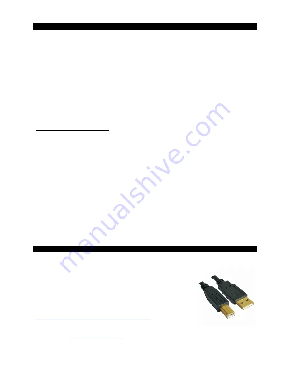
To be able to set up a connection with your PC use a readymade cable from
the local computer shop that has on one end the house type USB connector
and on the other side the flat one that PC’s can accept. (See picture)
By connecting the Airmate-USB to your PC the PC will recognize the Airmate
as new hardware and will establish a connection to the right program.
No need to download drivers, no complicated setup routines, just plug in the
USB cable into your Windows or Mac computer and start tracking!
If you first want to know more about USB try this link
http://en.wikipedia.org/wiki/Audio_Stream_Input/Output
If you’re pretty more familiar with audio recording, the latest versions of
Kristal Audio Engine and Audacity are available free of charge — just type in the following link in your
internet browser
http://www.asio4all.com/
and start downloading.


