W E B S T A T I O N M a n u a l P a g e 20
9
MASTER BACKPANEL CONNECTORS
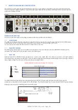
The master connector panel houses 12 RCA/Cinch connectors, 2 jack sockets, 3 male XLR connectors and 2x USB connector.
There is one power supply connectors. From left to right we will describe the functions and features of the master connector
panel as seen below in detail.
POWER CONNECTOR
This Euro connector accepts an AC voltage in between 85 volts and 260 volts at 50/60Hz.
9.1
CRM SEND
The CRM (Control Room Monitor) outputs are on two RCA Cinch connectors carrying the signal coming from the CRM volume
potentiometer on the front panel and its associated source selection. The level is 0 dBu (0.775 volt).
You can connect the inputs of active monitors to these Cinch connectors.
9.2
MASTER (SEND)
The PROG (Program) outputs are on two RCA Cinch connectors. This is also the case when the NON STOP ON-AIR switch is
activated. Then these main Cinch connectors carry the USB-3 signal.
9.3
MIC ON
Directly beneath the MASTER cinch connectors is a stereo jack socket (Mic On) that can control a red light indicator.
This stereo jack is connected to an OPTO-FET. This FET switch is capable of controlling external Red light circuits as long as it doesn’t
take a higher voltage than 24 volt and the current doesn’t exceed 50 mA!
NEVER CONNECT 115/230 AC VOLTAGE TO THIS JACK!!
Start / Mic-On Jack
Functions Opto coupler
Tip
Connected to opto-coupler
Ring
Connected to opto-coupler
Sleeve
Not connected
Our D&R ON-AIR warning light can be connected directly to the MIC-ON jack socket be-tween tip and ring by way of a
simple 2 wire connection, see the manual of the ON-AIR light. The ON-AIR led light has its own external 12volt DC power adapter.
Below you see a circuit for ON-AIR lights that need AC power.


