W E B S T A T I O N M a n u a l P a g e 21
10
SET-UP ROUTINES MODULE 1-2
•
Connect a power-amp, recorder, or transmitter to the Master left/right main outputs.
•
Connect a high impedance (NOT BELOW 32 Ohm) headphone to the “phones” jack socket
on the master section.
•
Connect a microphone or line level equipment.
•
Now, connect turntables (with built in RIAA pre-amps), CD players, and jingle machines.
•
Connect a red light indicator to the master section’s Mic On jack when there is a need for it.
•
Now with everything connected, follow the adjustment procedure.
•
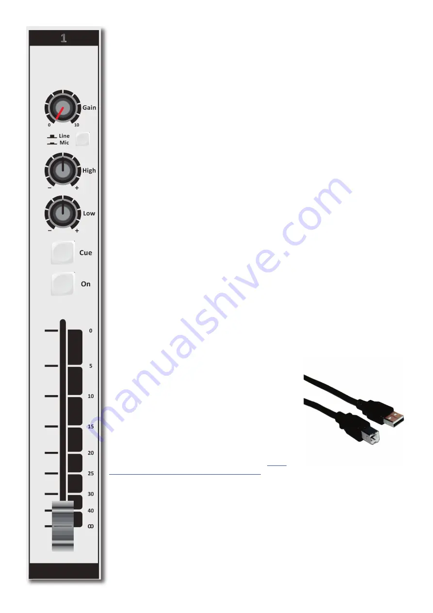
Note; for mikes, only activate the grey Mic switch, for line level, leave this switch up.
•
Put on your headphones and turn the headphone volume control to the “12 o’clock” position.
•
Set all the gain-controls to its minimum.
•
Set all equalizer-controls to the “12 o’clock” position.
•
Connect your mains power cable and switch the console on, on the back panel.
All switches will light for a short moment and the NON STOP will stay on.
10.1
SETTING UP AN INPUT CHANNEL
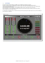
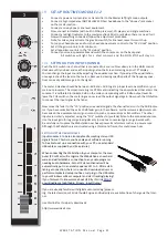
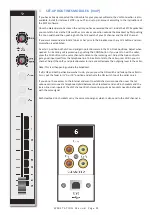
Push the CUE switch in a channel that is connected to a source. Now slowly turn the GAIN control
clockwise until you hear and see the input signal on the Screen metering on your TFT display.
You can change the input sound by adjusting the equalizer-section. If you adjust the equalization,
once again check the level on the meters, because increasing specific parts of the frequency spec
-
trum can easily add more gain to the signal.
The meter indication should be between -6 dB and +3 dB to get a proper level on amplifiers or your
main out processor. The screen metering is a PPM meter indicating the absolute level that enters the
console. It is calibrated to indicate 0 dB on the scale corresponding with a 0 dBu output level. Re
-
lease the CUE switch so the metering can now read the output signal again. Now push the ON button
to connect the input signal to the fader.
Now move the fader to the “10” position screened alongside the channel faders or to the 0dB indica
-
tor if you have cancelled the extra 10dB fader gain in the software. Further volume adjustments can
be made on the equipment your signal is send to, such as power-amps or transmitters. The other
inputs are similarly adjusted, using the “CUE” switches to (pre fade) listen to the connected sources.
Use the input gain for regular gain adjustments to create a convenient gain range to work with.
Be carefully not to place the Webstation near heavy power transformers such as in power amps.
Although the Webstation is constructed using a thick metal frame, this could cause hum.
SETTING UP THE USB MODULES
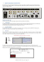
Input modules 3 to 5 are also capable of accepting stereo USB
signals from a PC where you have play-out software running.
To be able to set up a connection with your PC, use a standard
USB cable as supplied by us (See picture).
When connecting the Webstation to your computer, the com
-
puter (PC or Mac) will recognize the Webstation as new hard
-
ware and will establish a connection to any audio programs
needing audio hardware. Also all 3 stereo channels will be
automatically put in a natural sequence of 1 to 3. After estab
-
lishing a connection, there is no need to down-load drivers or
perform complicated setup routines. Just plug in the USB cable
to your Windows or Mac computer and start tracking/playing!
If you first want to know more about USB try this link http://
en.wikipedia.org/wiki/Audio_Stream_Input/Output
If you are already familiar with digital audio recording/process
-
ing, the latest versions of Kristal Audio Engine and Audacity are available free of charge via the Inter
-
net.
Use this link for third party downloads:
http://www.asio4all.com


