background image

Operator's Manual for DM100 VDR and DM100 S-VDR G2

Copyright Danelec Marine A/S

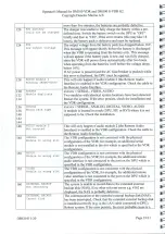
defective/misconfigured

NAS.

Missing (SI08-12)

board

in the DPU. The most

probable

cause

is

that

the SAP

board

in the DPU is defective.

DBS11011-20

Page 24/31

=

=

=

-=

170

|AUDIO

:

:

:

.

ed

Recording muted

Recording of

audio has been stopped due

to

manual intervention

==

172

[NETWORK

Data

Too much network data

is

being

transmitted

to

the

VDR.

Network

=

Accumulated Excess

data in this context does

not

include image data. Try to determine

Ee

what

is wrong using the

VDR

Explorer

i.e.

check what

has been

—-

received

on NI200

NI215

180

[SYSTEM

The VDR

is

in service

mode.

It

is possible

to

make

changes

to

the

-=

in Service

Mode

VDR

configuration.

When this

is

done, the mode switch on

the

=

DPU front must be set to

position

“Normal operation”.

:

182;

[BCE

i

The

DPU

is

unable

to communicate with the Bridge Control

=

Communication

error

pane]

Check the cable from

the

DPU to

the

BCP.

Reboot

the

Es

system.

If

the error persists, the

most probable

cause is a faulty

-

cable

or

BCP.

184

|BAM

)

The communication to the Bridge Alert Management

system

has

BAM

comm.

timeout

been

interrupted.

190

|DFU

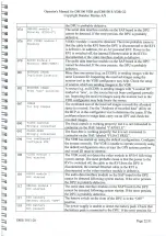
The primary fan in the DPU has failed. The secondary fan

in

DPU

Es

Se

will

serve as a backup until

the

problem is rectified. The

VDR

will

ly

be able to operate normally unless the secondary fan also fails

(error

191).

This problem

must

be

rectified

latest at the next APT.

-=

191

|DEU

The secondary fan in the

right

side

of

the DPU has failed. This

is

il

Backup:

fan

failed

only a

major

problem

if

the

primary

fan has also failed (error 190).

300-

|SERIAL

Mandatory serial data is

not

being received. Check

that

the source

-—

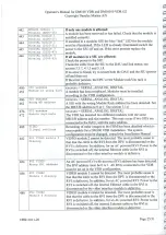
307

|

ZAmecut on

Sax

is

on. Check

the

signal

from the source (serial monitor in VDR

|

explorer,

WEB

status

or VGA status display).

If

no signal

is

-=

present

check the cable and make sure

that

the configuration

is

correct.

=

320-

|NETWORK

Channel

Mandatory network data

is

not

being

received

on channel NI2xx.

=

335,

|Timeout

on

NIZxx

Check

that

the source is switched on and active, check the cable

and

that

the VDR configuration is correct.

360-

[NETWORK

Channel

Too much

network

data is currently being

received

on channel

=

375

|Excess

Data

on NIZxx

|NJoxx

Check

that the source

is

operating correctly. The VDR

Explorer

may be used

to monitor

the data.

=

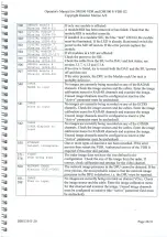
400-

|

SERIAL

Mandatory serial data

is

not being received. Check

that

the source

43]

[Timeout

on

SIxx

is on. Check the signal from

the

source (serial

monitor

in VDR

—a

explorer, WEB status

or

VGA status display).

If

no signal

is

=

present check

the cable and make sure

that

the configuration

is

correct.

=

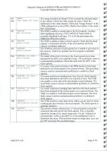
44]

|SERIAL

module

2

For a DM100, the second serial

module

is

integrated on

the

SAP

=

—a

—-

—-=

==

—-=

pt

Summary of Contents for DM100 VDR

Page 1: ...CRC EE EE Err rrr rrr rr eee danelec EEEEEEEE MARINE Operator s Manual for DM100 VDR and DM100 S VDR G2 Document Number DBS11011 Version Number 2 0 Date June 2019 P N hard copy 9302721 20...

Page 2: ...iginal issue of document 31 May 2014 Minorrevision 1 2 June 2014 Minorrevision 1 3 May 2016 Updateoferror text for error 054 and 184 1 4 September 2018 Description of Remote Audio Interface included D...

Page 3: ...ceviiiiiiiiiiiiiicieecceeeee eee 11 3 2 Operation of the DM100 DAU ccucosissssssssssmssmsimssamammmimmamsiimmmmmatimaios 12 3 3 Data Processing Unit DPU ccmsimmissimmmmsisssssissinmssesmsmsmnsississis...

Page 4: ...interfaces ococooveoovoooooo 18 5 1 6 MR AAAIESS ceeiicieiiee eeeeee eee eee eee18 6 OPERATION OF STANDARD RVI 02 004 AND RVI 02 004D POE 19 Ly T OPERATION OF THE RAL cotturieureeesesesessssssssssesss...

Page 5: ...G2 Installation Manual for Remote Video Interface with PoE RVI 02 004 RVI 02 004D Installation Manual for DM100 DM400 modular Sensor Interface Unit 1 2 Terms and Abbreviations BCP BMU DAU DPU OPT SIU...

Page 6: ...System overview typical configuration 2 1 1 Data Acquisition Unit DAU The Data Acquisition Unit contains the Data Processor Unit DPU The DAU must be installed indoors in the proximity of the bridge 2...

Page 7: ...able to send images to the VDR using Ethernet i e typically older equipment The RVI must be installed indoors normally close to the RADARS It must be connected to the DAU with a cable which may be up...

Page 8: ...compared to a VDR The typical S VDR installation is therefore simpler Float free Ethernet PoE capsule STP CATS Fixed o Ethernet PoE DAU BCP SIECATS J Ethernet STP CATS CAT6 Images from RADAR BMU Ethe...

Page 9: ...for a DM100 VDR and a DM100 S VDR G2 islisted below Type of input Maximum configuration Ethernet interfaces 7 on DAU Serial inputs 36 12 on DAU 3 modules Analog inputs 32 Digital inputs 128 Audio inp...

Page 10: ...When the cause of erroris resolved the alert message will be cleared and the caution indicator turned off 3 1 2 Self test Operational Performance Test An Operational Performance Test OPT of the VDR mu...

Page 11: ...stick must be formatted with a file system supported by Windows 7 or 10 FAT32 or NTFS On the BCP go to Menu Downioad data to USB disk and press OK Two options are possible Download of VDR data downlo...

Page 12: ...anual is only relevant during installation and service Program AC breaker AC inlet UF for I F for memory N Xi capsule float free Servi VGA USB UF for UFfor UF for IF for IF to CIVICS interface pon su...

Page 13: ...rcontrol circuit is OK operating OK LED blue Steady light Power to DPU present OK Off No power to the DPU Error note 1 3 3 2 AC breaker The AC breaker is a combination of a fuse and a manually operate...

Page 14: ...ion Contact a service agentifthe problem cannot be rectified 3 3 6 Main CPU LED The main CPU LED is controlled by the power control circuit which will become active as the first circuit after poweris...

Page 15: ...log I F Digital I F Uni rack with 16 analog interfaces 4 1 LEDs on the Uni rack 41 1 ACLED Indicates the power AC is present 4 1 2 AC breaker The AC breaker is a combination of a fuse and a manually o...

Page 16: ...4 1 3 Ethernet link and activity indicators The LINK LED right will be illuminated yellow when a communication link is established to the DAU The ACT LED left will flicker green depending on the traff...

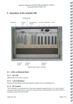
Page 17: ...s 5 1 LEDs on Module Rack 5 1 1 ACLED Indicates the power AC is present 5 1 2 Link indications Indicates that the Module Rack has detected a module in the corresponding slot 5 1 3 AC breaker The AC br...

Page 18: ...LED is not used Please notice that the behavior of the LEDs is different from other parts of the system for example the DAU 5 1 5 Allocation of system labels for digital interfaces Card number in VDR...

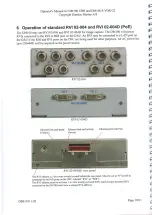
Page 19: ...other purposes An AC powerkit p n 2304449 will be required as the power source RVI 02 004D Ethernet link and speed Ethernet link and activity Ethernet port with PoE Yellow Green RVI 02 004 D rear pane...

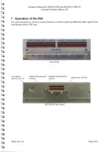
Page 20: ...S 7 Operation of the RAI For some installations a Remote Audio Interface is used for capturing additional audio signals from microphones and or VHF sets RAI 08 001 RAI address Ethernetlink and speed E...

Page 21: ...s on the audio interface module with a spare microphone Replace microphones which are reported faulty if no other erroris discovered 058 AUDIO One or more microphones are using too much power The cabl...

Page 22: ...the received images exceeds the allocated Toc big images space in a record Use the Analysis of recorded data utility on the BCP or in the configuratortool to determine the cause If the problem relate...

Page 23: ...NALOG DIGITAL VIDEO AUDIO 1387 Wzeng rackitype A module is located in a rack DPU SIU or RVI where it is not 140 supposed to be Check the installation 142 144 146 AUDIO module 2 This will only happen i...

Page 24: ...l the problem is rectified The VDR will ly be able to operate normally unless the secondary fan also fails error 191 This problem must be rectified latest at the next APT 191 DEU The secondary fan in...

Page 25: ...the DAU with the same address 480 VIDEO Recording of radar imagesto the FRM has been disabled which is Tllegal settings unacceptable for a DM100 VDR installation The system configuration must be chang...

Page 26: ...re currently being recorded on any of the ECDIS ECDIS ng input channels Check the image sources and the cables Enter the image calibration menu for RADAR channels and examine the image Unused image ch...

Page 27: ...any write errors writing to the FRM memory have been Wrlfes srrers detected by the fixed capsule over a period of time The most likely cause is serious communication problems or a defective fixed caps...

Page 28: ...been MILES RrroLs detected by the DPU over a period of time The most likely cause is communication problems Check the cable from the DPU to the float free capsule 725 FLOAT FREE too many Too many wri...

Page 29: ...he error persists the DPU must be repaired 745 LONG TERM too many write errors Too many write errors writing to the VDR data disk have been detected by the DPU over a period of time The most likely ca...

Page 30: ...heaE ped wp system If the errorpersists then call for assistance 971 SELF TEST Required networking interfaces are not available to start the VDR Xx network Restart the system Ifthe error persists the...

Page 31: ...1 2302786 3000671 3302519 7302532 7304878 9302376 9302719 DBS11011 20 Description Uni Rack UR 06 002 8ch analog RVI with PoE for DM100 2 x 5 x BNC RVI with PoE for DM100 2 x DVI I MK4 capsule with cra...

Reviews: