Operator's Manual for the DM100-2014 VDR
Copyright Danelec Marine A/S
2 System overview
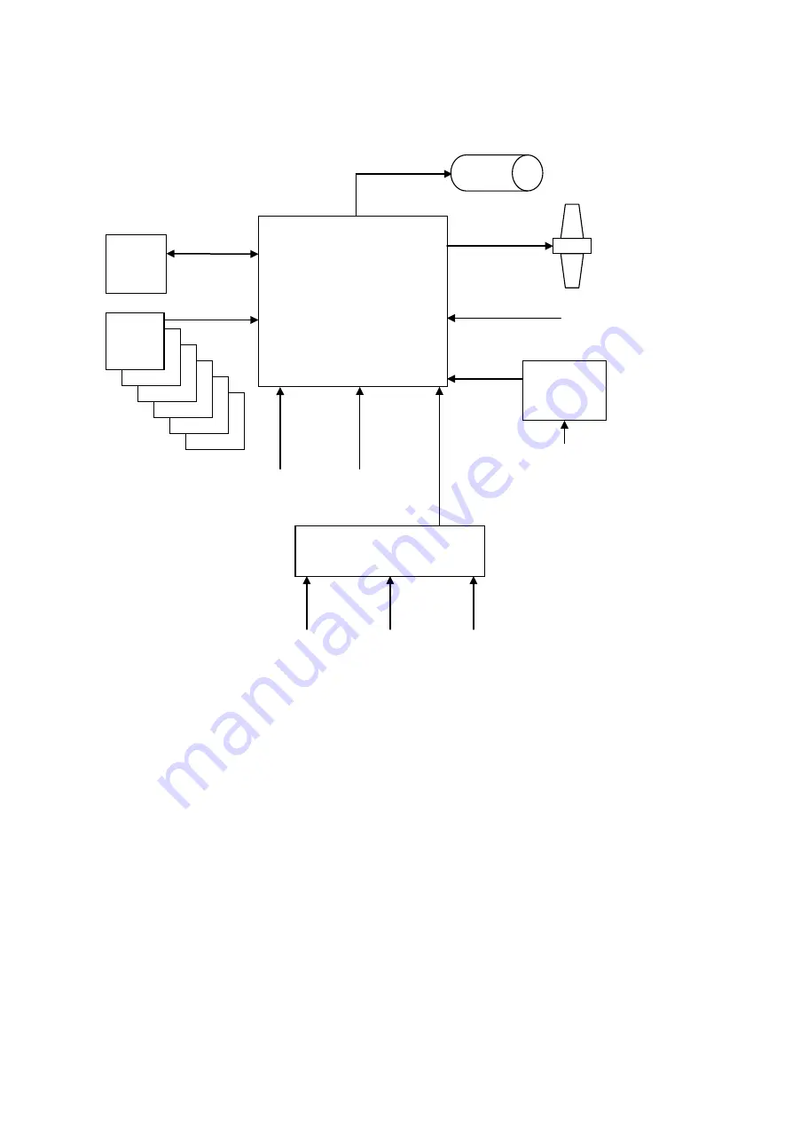
VDR System overview (typical configuration)
2.1.1 Data Acquisition Unit (DAU)
The Data Acquisition Unit contains the Data Processor Unit (DPU). The DAU must be installed
indoors in the proximity of the bridge.
2.1.2 VDR Bridge Control Panel (BCP)
The BCP must be installed on the bridge either in a console or mounted on a bulkhead. The BCP is
the interface for the VDR Operational Performance Test which must be carried out regularly. VDR
system errors will also be shown here as a caution (steady yellow light).
2.1.3 Bridge Microphone Units (BMU)
A number of BMUs must be installed on the bridge (console, ceiling or bulkhead mounted).
Watertight outdoor BMUs for the bridge wings are available.
BMU
BMU
BMU
BMU
BMU
DAU
Fixed
Capsule
BMU
SIU
Digital inputs (64)
BCP
Ethernet
STP CAT5
VHF
6 x BMU
Serial inputs (8)
Video inputs (2)
Analog or DVI from
e.g. RADAR
Optional
Remote
Video I/F
Ethernet PoE
STP CAT5
Serial inputs (12)
e.g. GPS
Analog inputs (8)
Ethernet PoE
STP CAT5
Ethernet PoE
STP CAT5
Ethernet PoE
STP CAT5
Ethernet STP
CAT5/CAT6
Images from
RADAR and ECDIS
Float-free
capsule
DBS11011-12
Page 6/27


