background image

Operator's Manual for the DM100 S-VDR 

Copyright Danelec Marine A/S 

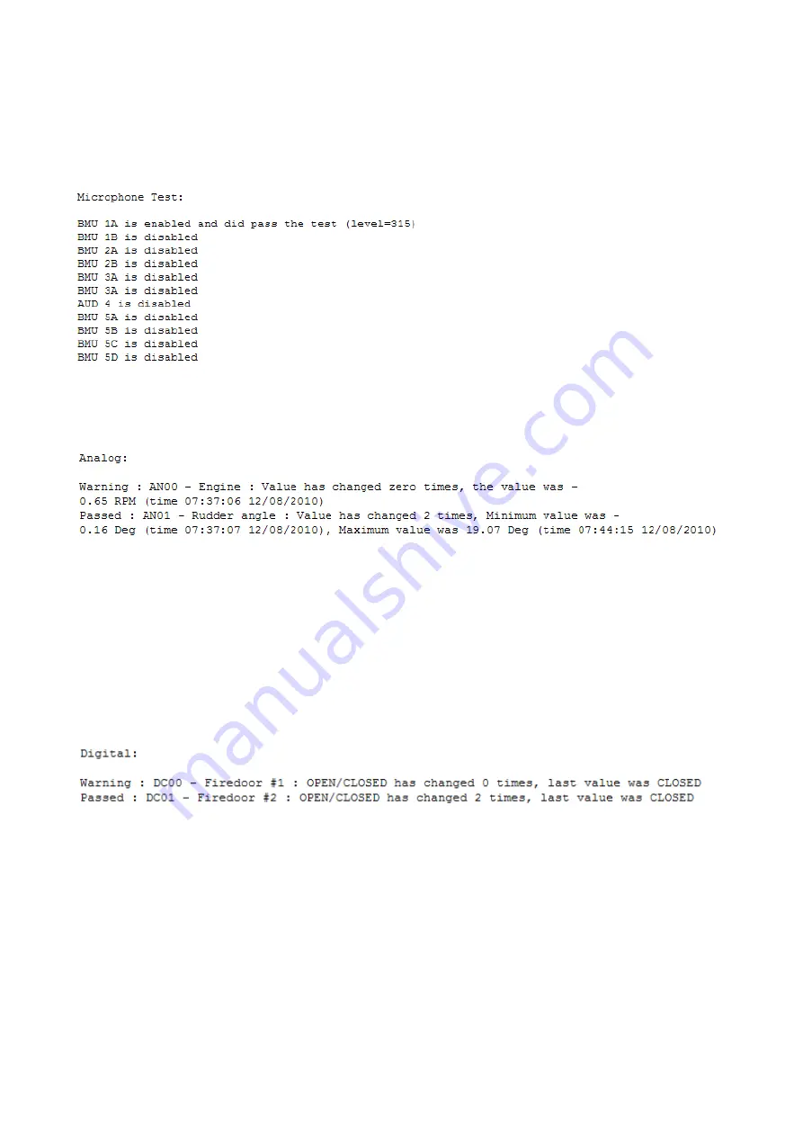
8.3.2.1  Verification of microphone functionality 

The self-test in the microphones is activated and the result is printed in the report – either passed or 

failed 


8.3.2.2  Verification of analog data 

The data on each enabled input is analyzed and the result is printed in the report 


Failed

: The input is not calibrated 

Warning:

 The input was steady – the current value is printed and must be checked – e.g. if vessel 

at harbor SOG should be close to 0  

Passed:

 The input has changed during the verification – the maximum and minimum value is 

printed and must be checked. 


8.3.2.3  Verification of digital data 

The data on each enabled input is analyzed and the result is printed in the report. 


Warning:

 The input was steady – the current value is printed and must be checked. 

Passed:

 The input changed during the verification – the current value is printed and must be 

checked. 


DBS10912-10 


Page 33/36 


Summary of Contents for DM100 S-VDR

Page 1: ...Operator s Manual For the DM100 S VDR Document Number DBS10912 Version Number 1 0 Date October 2014 P N hard copy 9302539 10 ...

Page 2: ...Operator s Manual for the DM100 S VDR Copyright Danelec Marine A S Revision record Version Date Description 1 0 October 2014 Original issue of document DBS10912 10 Page 2 36 ...

Page 3: ...it 9 3 1 1 Alarm display 9 3 1 2 Method for initiating a backup on the VDR data disk 9 4 OPERATION DM100 DAU 11 4 1 DPU 12 4 1 1 Power LEDs 12 4 1 2 AC breaker 12 4 1 3 AC inlet 12 4 1 4 Battery switch 13 4 1 5 VDR status LED 14 4 1 6 Main CPU LED 14 4 1 7 LEDs in the Ethernet connectors 14 5 OPERATION OF STANDARD RVI 02 004 AND RVI 02 004D POE 15 6 OPERATION OF RVI WITH AC POWER SUPPLY 16 6 1 1 R...

Page 4: ... of the S VDR functionality following service on any sensor 25 8 2 Setting the IP address of the PC windows 7 26 8 3 Connecting the PC to the S VDR 29 8 3 1 Run the VDR Verifier program 29 8 3 2 Examination of the report 32 8 4 List of most common spare parts 36 DBS10912 10 Page 4 36 ...

Page 5: ...nual for DM100 S VDR DBS10911 Inspectors and Authorities Manual for DM100 S VDR DBS10919 Installation manual for Remote Video Interface RVI 02 004 D 1 2 Terms and Abbreviations BAU Bridge Alarm Unit BMU Bridge Microphone Unit DAU Data Acquisition Unit DPU Data Processing Unit located inside the DAU SIU Sensor Interface Unit RVI Remote Video Interface NAS Network Attached Storage option used for ex...

Page 6: ... in a console or mounted on a bulkhead System errors will generate a visual and audible alarm 2 1 3 Bridge Microphone Units BMU A number of BMUs must be installed on the bridge console ceiling or bulkhead mounted Watertight outdoor BMUs for the bridge wings are available 2 1 4 Fixed Data Capsule The data capsule the orange box must be installed on an external deck close to the vessel s center line...

Page 7: ...o the fixed data capsule a float free capsule may be used instead 2 1 6 Remote video interface RVI RADAR video is acquired using a Remote Video Interface RVI The RVI must be installed indoors typically close to the RADARs It must be connected to the DAU with a cable which may be up to 100m long DBS10912 10 Page 7 36 ...

Page 8: ...ent may be used to make larger or non standard configurations The maximum number of supported interfaces for an S VDR is listed below Interface type Maximum configuration Serial inputs 28 12 on DAU 2 modules Analog inputs 32 2 modules Digital inputs 128 8 modules Audio inputs 18 10 on DAU 8 on RAI Video inputs 4 2 RVIs DBS10912 10 Page 8 36 ...

Page 9: ...ven if is contains many errors Repetitive alarms are marked with an R after the error code The repetitive error status for a failed system component data source will be automatically reset if no error has been generated for 12 hours The Purge List button on the BAU will force reset of repetitive error status for all system components data sources 3 1 1 2 Dimming The button with the light bulb symb...

Page 10: ...rmal circumstances Alternatively data from the disk must be transferred to another media and space on the disk can be manually released This requires proper authorization and cannot be done from the BAU The VDR data disk which is easily removed from the DAU must be retrieved if the vessel is abandoned after a serious incident DBS10912 10 Page 10 36 ...

Page 11: ...rvice or if the USB VDR data disk has to be removed following a serious incident VDR status LED AC inlet USB VDR data disk Program memory I F to IAS I F for BAU Service console Ethernet ports VGA interface Audio interfaces DPU AC breaker Power status LEDs Battery switch Interfaces for serial data Termination resistors for SI00 SI03 Main CPU status LED Service mode switch I F for capsule I F for RD...

Page 12: ...d Error ERR LED red Steady light The internal power control circuit has failed Error Off The internal power control circuit is operating OK OK LED blue Steady light Power to DPU present OK Off No power to the DPU Error note 1 4 1 2 AC breaker The AC breaker is a combination of a fuse and a manually operated switch i e it can be used to manually switch off the AC power sources but it will also pop ...

Page 13: ... battery switch indirectly controls a relay between DPU and the battery pack When switching the S VDR off do the following Pop out the AC breaker and move the battery switch to its OFF position shortly Move the battery switch back to its ON after the S VDR is turned off DBS10912 10 Page 13 36 ...

Page 14: ...n CPU LED is controlled by the power control circuit which will become active as the first circuit after power is applied The power circuit uses the LED to show information about the main CPU OFF The power circuit is not started yet should only take a few seconds OK Green 1Hz The power circuit is waiting for the main CPU to start boot load may take up to two minutes OK Steady green The main CPU is...

Page 15: ...004 and RVI 02 004D for image capture Another type exists see section 6 which may be used if the Power over Ethernet ports on the DPU are used for other purposes RVI 02 004 RVI 02 004D RVI 02 004 and RVI 02 004D rear panel Ethernet link and activity Green Ethernet link and speed Yellow RVI address 0 or 1 second RVI Ethernet port with PoE DBS10912 10 Page 15 36 ...

Page 16: ...or 1 if it is the second RVI 6 1 2 Ethernet ports ETH A must be connected to the DAU Notice that the LEDs in the Ethernet connectors RJ45 are inactive for this unit 6 1 3 ST LED The Status LED Yellow will flash 1Hz after power on and then become steady if a communication link is established to the DAU The LED will always switch itself off after one minute RVI address Ethernet port ST LED AC inlet ...

Page 17: ...mmunicate with BAU 2 of 2 Check the cable from the DPU to the BAU Reboot system Also check switch settings on BAU 2 Switch 1 should be OFF switch 2 ON If the error persists call for assistance The most probable cause is a faulty cable BAU or DPU 036 CONFIG Unable to save The VDR was unable to save the configuration Please retry This error is only expected to occur during configuration installation...

Page 18: ... calibration menu for that channel and examine the image Unused video channels must be configured inactive the Active parameter must be unchecked 088 090 092 094 VIDEO VD0n image too big The radar image exceeds the allocated space in the capsule and the system is therefore unable to record for 12 hours Check the radar image for noise Check the calibration of the video channel Reduce the number col...

Page 19: ...in the slot which is specified in the VDR configuration 150 AUDIO Module in wrong slot The VDR configuration is not consistent with the physical configuration of the VDR e g the additional remote audio interface is not connected to the port on the DPU which is specified in the VDR configuration 152 VIDEO Module in wrong slot The VDR configuration is not consistent with the physical configuration o...

Page 20: ...oo small The configured incident record size on the VDR data disk is too small for storing the capsule data Change the incident type to large incident or replace the capsule for one with lower memory capacity 562 INTERNAL BACKUP Backupdisk too small The capacity of the VDR data disk is too small for internal extended backup Change the VDR data disk or disable this feature 609 STORAGE Device resets...

Page 21: ...ed correctly A certifed service technician can fix this 654 INTERNAL BACKUP WR errors level 1 Too many write errors writing to the VDR data disk have occurred within a given interval Retrying to write data fixed the problem The most likely cause is communication problems The VDR data disk is not taken out of service and data is still recorded 655 INTERNAL BACKUP WR errors level 2 Too many write er...

Page 22: ...data too big The amount of data received by the VDR exceeds the capacity of the fixed capsule This is typically caused by receipt of too much image data Use the Analysis of recorded data utility on the BCP or in the configurator tool to determine the cause If the problem relates to image data carry out an OPT and check the recorded images 711 CAPSULE Wrong Attachment The capsule is connected to th...

Page 23: ...he SIU power off and then on If the error persists the DPU or the Module rack Uni rack is probably defective 443 DIGITAL module 1 Missing DI00 15 444 DIGITAL module 2 Missing DI16 31 445 DIGITAL module 3 Missing DI32 47 446 DIGITAL module 4 Missing DI48 63 450 452 SIU xxxxxxx Module in wrong slot xxxxxxx SERIAL ANALOG DIGITAL A module has been misplaced Modules must be installed according to the V...

Page 24: ...If all modules in the SIU are affected Check the power to the SIU Check the cable from the SIU to the DAU and link status see section 4 1 7 Error Reference source not found and Error Reference source not found If no error is found try to restart both the DAU and the SIU power off and then on If the error persists the DPU or the Module rack Uni rack is probably defective 501 DIGITAL module 5 Missin...

Page 25: ...the S VDR is verified followed service on any sensor e g the GPS connected to the S VDR The bridge alarm panel will display obvious errors if for example the signal from a sensor sending NMEA sentences is missing completely However it is required that recorded data is retrieved and checked to a certain extent A tool for doing that is stored on the S VDR and may be downloaded via a web browser to t...

Page 26: ...f the S VDR is 10 0 0 100 255 255 255 0 The PC must use an IP address within the same range Note The operator may have changed the IP address for the S VDR This must be documented on label inside the door of the main unit DAU Open the control panel for the Network and Sharing Center Click on Change adaptor settings DBS10912 10 Page 26 36 ...

Page 27: ...for the DM100 S VDR Copyright Danelec Marine A S Right click on the icon representing your Ethernet adaptor and select Properties from the drop down menu Open the Properties for Internet Protocol 4 DBS10912 10 Page 27 36 ...

Page 28: ...erator s Manual for the DM100 S VDR Copyright Danelec Marine A S Set the new IP address for the PC and click on OK It is a good idea to write down the previous settings Click on OK DBS10912 10 Page 28 36 ...

Page 29: ...the S VDR using a standard CAT5 patch cable Open an Internet browser on the PC Type in the IP address of the S VDR in the browser address field The IP address of the S VDR is 10 0 0 100 default 8 3 1 Run the VDR Verifier program Click on the Download VDR Verifier link Click Run to start the program DBS10912 10 Page 29 36 ...

Page 30: ... that a connection can be made to S VDR Select the duration of the recording to be verified Duration can be set from 15min to 720min Please notice that duration is limited to the time since the last restart of the S VDR and that only the radar images recorded to capsule will be checked The best result is obtained if the data to be verified was recorded during a voyage Verification of 15 minutes of...

Page 31: ...or s Manual for the DM100 S VDR Copyright Danelec Marine A S Select a folder for the report and data files Wait for the verification to finish Press Yes to open report in a web browser DBS10912 10 Page 31 36 ...

Page 32: ...Operator s Manual for the DM100 S VDR Copyright Danelec Marine A S 8 3 2 Examination of the report The following tests have been made The report starts with a summary DBS10912 10 Page 32 36 ...

Page 33: ...calibrated Warning The input was steady the current value is printed and must be checked e g if vessel at harbor SOG should be close to 0 Passed The input has changed during the verification the maximum and minimum value is printed and must be checked 8 3 2 3 Verification of digital data The data on each enabled input is analyzed and the result is printed in the report Warning The input was steady...

Page 34: ...A graphical representation of data from each track is shown as additional information Data for tracks with no active microphones which are not configured to record VHF radio communication is omitted 8 3 2 5 Verification of serial data The data on each enabled input is analyzed and the result is printed in the report i e the list of NMEA formatters defined in the S VDR configuration is compared wit...

Page 35: ... contains information Error The image contains little or no information The last four images from each active input are saved and must be checked before a conclusion is made 8 3 2 7 Verification of power sources The presence of AC mains the battery and optional DC is checked 8 3 2 8 Verification of alarm status A list of S VDR alarms which were present while the data was recorded will be displayed...

Page 36: ...ith PoE for DM100 2 x 5 x BNC 1302365 RVI with PoE for DM100 2 x DVI I 1302373 Fixed capsule MK4 1302958 Float free capsule MK1 2302786 Battery pack and fans 2 for DM100 2302144 USB backup drive for DM100 S VDR 2302807 Ethernet Interface for Capsule MK4 3000671 Beacon replacement kit 3302519 50m zero halogen FTP CAT5 cable from DPU to MK4 fixed capsule or float free capsule 7302530 Boot flash for ...

Reviews: