AK-CT
450A
User
Guide RS8GR602 © Danfoss 2016-10
19
Survey of functions
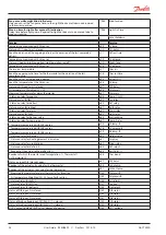
Function
Para-
meter
Parameter by operation via data
communication
Normal display
Normally the temperature value from one of the two thermostat sensors S3 or S4 or
a mixture of the two measurements is displayed.
In o17 the ratio is determined.
Display air (u56)
Thermostat
Thermostat control
Set point
Regulation is based on the set value plus a displacement, if applicable. The value is set
via a push on the centre button.
The set value can be locked or limited to a range with the settings in r02 and r 03.
The reference at any time can be seen in "u91 Cutout temp".
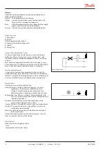
Cutout °C
Differential
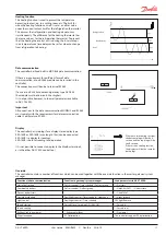
When the temperature is higher than the ref the set differential, the
compressor relay will be cut in. It will cut out again when the temperature comes
down to the set reference.
r01
Differential
Setpoint limitation
The controller’s setting range for the setpoint may be narrowed down, so that much
too high or much too low values are not set accidentally - with resulting damages.
To avoid a too high setting of the setpoint, the max. allowable reference value may
be lowered.
r02
Max cutout °C
To avoid a too low setting of the setpoint, the min. allowable reference value may
be increased.
r03
Min cutout °C
Correction of the display’s temperature
If the temperature at the products and the temperature received by the controller
are not identical, an offset adjustment of the display temperature can be carried out.
r04
Disp. Adj. K
Temperature unit
Set here if the controller is to show temperature values in °C or in °F.
r05
Temp. unit
°C=0. / °F=1
(Only °C on AKM, whatever
the setting)
Correction of signal from S4
Compensation possibility due to long sensor cable
r09
Adjust S4
Correction of signal from S3 and S3B
Compensation possibility due to long sensor cable
r10
Adjust S3
Start / stop of refrigeration
With this setting refrigeration can be started, stopped or a manual override of the
outputs can be allowed. (For manual control the value is set at -1. Then the EVR outlet
and the relay outlets can be force-controlled by the respective reading parameters
(u23, u58, etc.). Here the read value can be overwritten.) Refer also to the menu
overview on page 33
Start / stop of refrigeration can also be accomplished with the external switch
function connected to a DI input.
Stopped refrigeration will give a ”Standby alarm”.
r12
Main Switch
1: Start
0: Stop
-1: Manual control of outputs allowed
Night setback value
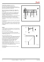
The thermostat’s reference will be the setpoint plus this value when the controller
changes over to night operation. (Select a negative value if there is to be cold
accumulation.)
r13
Night offset
Thermostat function
Here it is defined how the thermostat is to operate. Either as an ordinary ON/OFF
thermostat or as a modulating thermostat.
1: ON/OFF thermostat
2: Modulating
When operation is ”modulating” the EVR valve will limit the flow of refrigerant so
that the temperature variation will be less than for the ON/OFF thermostat.
The differential (r01) must not be set lower than 2K for "modulating".
In a decentralised plant you must select the ON/OFF thermostat setting.
r14
Therm. mode
Selection of thermostat sensor
Here you define the sensor the thermostat is to use for its control function. S3, S4, or
a combination of them. With the setting 0%, only S3 is used (Sin). With 100%, only S4.
r15
Ther. S4 %
Ref. Dif.


