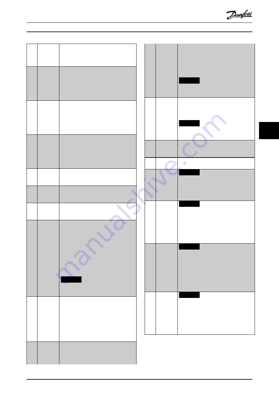
[71]
Mech.
Brake
Feedback
inv.
Inverted brake feedback for hoisting
applications.
[72]
PID error
inverse
When enabled, this option inverts the
resulting error from the process PID
controller. Available only if
parameter 1-00 Configuration Mode
is set to
[6] Surface Winder
,
[7] Extended PID Speed OL
,
or
[8] Extended PID Speed CL
.
[73]
PID reset I-
part
When enabled, this option resets the I-part of
the process PID controller. Equivalent to
parameter 7-40 Process PID I-part Reset
.
Available only if
parameter 1-00 Configuration
Mode
is set to
[6] Surface Winder
,
[7] Extended
PID Speed OL
, or
[8] Extended PID Speed CL
.
[74]
PID enable
Enables the extended process PID controller.
Equivalent to
parameter 7-50 Process PID
Extended PID
. Available only if
parameter 1-00 Configuration Mode
is set to
[7] Extended PID Speed OL
or
[8] Extended PID
Speed CL
.
[80]
PTC Card 1 All digital inputs can be set to
[80] PTC Card
1
. However, only 1 digital input must be set
to this option.
[91]
PROFIdrive
OFF2
The functionality is the same as the
corresponding control word bit of the
PROFIBUS/PROFINET option.
[92]
PROFIdrive
OFF3
The functionality is the same as the
corresponding control word bit of the
PROFIBUS/PROFINET option.
[94]
Light Load
Detection
Light load detection is a feature for lift
application to ensure that the lift runs in the
evacuation direction which requires the least
energy (UPS capacity), during an emergency.
See parameters
parameter 30-25 Light Load
Delay [s]
,
parameter 30-26 Delay Before
Measurements
,
parameter 30-27 Light Load
Speed [%]
,
parameter 30-28 Evacuation Speed
[%]
, and
parameter 30-29 Ramp Time
for light
load detection configurations.
NOTICE
Flying start overrules light load
detection.
[95]
Evacuation
Evacuation Mode is a feature for lift
application to enable drives to operate at
reduced DC-Voltage for evacuation of the
people in case of power failure. When the
feature is activated, under-voltage limits and
enable voltage limits is reduced so that the
drive can be operated with 230V single phase
UPS-supply.
[96]
Mains Loss
Select to improve kinetic back-up.
When the mains voltage goes back to a level
that is close to (but still lower than) the
detection level, the output speed increases
and kinetic back-up remains active. To avoid
this situation, send a status signal to the
frequency converter. When the signal on the
digital input is low (0), the frequency
converter forcibly turns off the kinetic back-
up.
NOTICE
Only available for pulse inputs at
terminals 32/33.
[97]
Mains Loss
Inverse
When the signal on the digital input is high
(1), the frequency converter forcibly turns off
the kinetic back-up. For more details, see the
description of
[96] Mains loss
.
NOTICE
Only available for pulse inputs at
terminals 32/33.
[98]
Start edge
triggered
Edge-triggered start command. Keeps the
start command alive. It can be used for a
start push key.
[100] Safe Option
Reset
Resets the safety option. Available only when
the safety option is mounted.
[106] Set Master
Home
NOTICE
This option is available only with
software version 48.XX.
Sets actual master position to the value of
parameter 17-88 Master Home Position
.
[107] Target
Inverse
NOTICE
This option is available only with
software version 48.XX.
Changes the sign of the set target position.
For example, if the set target is 1000, the
activation of this option changes the value to
-1000.
[108] Enable
Master
Offset
NOTICE
This option is available only with
software version 48.XX.
Activates the master offset selected in
parameter 3-26 Master Offset
when
parameter 17-93 Master Offset Selection
has a
selection from
[1] Absolute
to
[5] Relative
Touch Sensor
.
[109] Enable
Vir.Master
NOTICE
This option is available only with
software version 48.XX.
Enable signal for the virtual master function.
Only applicable when
option [10] Synchroni-
zation
is selected in
parameter 1-00 Configuration Mode
.
Programming
Design Guide
MG80C602
Danfoss A/S © 05/2019 All rights reserved.
43
6
6
Summary of Contents for AHF 010
Page 2: ......


