Operation
On AKA 245 there are no buttons. The unit is ex clusively operated via control panel type AKA 21 or
system software type AKM.
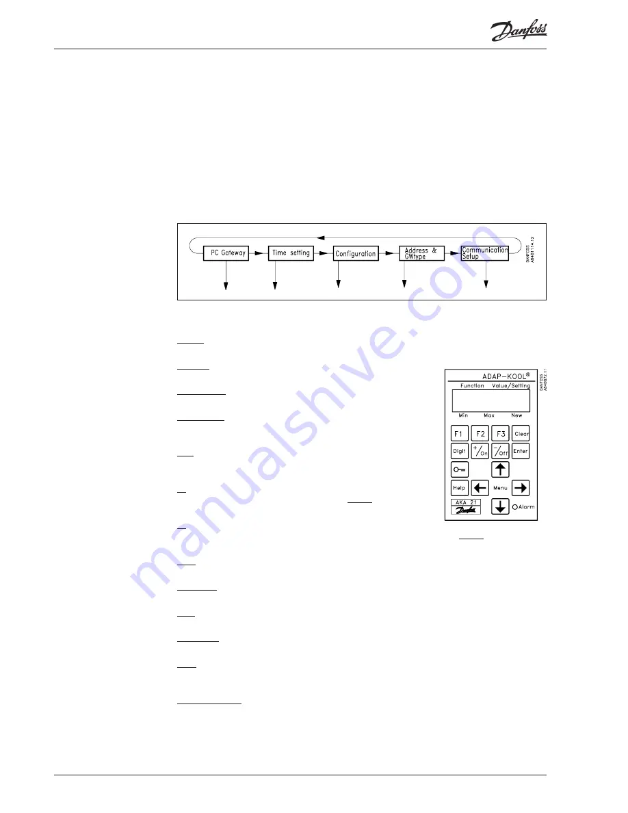
Operation from AKA 21 takes place via a menu system coded into the gateway.
The gateway menu structure has been “lowered” in relation to the menu struc ture of the AKC
controllers. Change between menus takes place by means of the control module’s arrow keys.
Display
The display in AKA 21 has two lines with 16 characters each.
Function
The fi eld describes the available menu.
Value/setting
The fi eld shows the current value.
Min and Max
The fi eld indicates the possible min. and max. values
of the setting.
New
In this fi eld a new value is selected. The fi eld will be
empty when there is a para meter that cannot be set.
F1
Used for displaying the “alarm list” found in the master gateway (address
125).*).
F2
Used for displaying the “NETWORK INFORMATION” (system table) found in the master gateway
(address 125).*)
Clear
Return to the gateway's access menu.
Arrow keys
Used for moving about in the gateway’s programme (menus).
Digit
Used for selecting the digit that has to be changed.
+/On , -/Off
Used for selecting a new value. It will either be a fi gure or a changeover bet ween on/off functions.
Enter
Used for confi rming new settings. If a changed display is left without “Enter” having been pushed, the
new value will not be stored.
F3, “key” and Help
Not used for gateway operation.
*
) If national characters and ID codes are used for alarm texts from AKC controllers, these characters
will not be presented correctly in the AKA 21 display.
Principle
Operation via AKA 21
22
Manual RS8DT102 © Danfoss 09/2004
AKA
245


