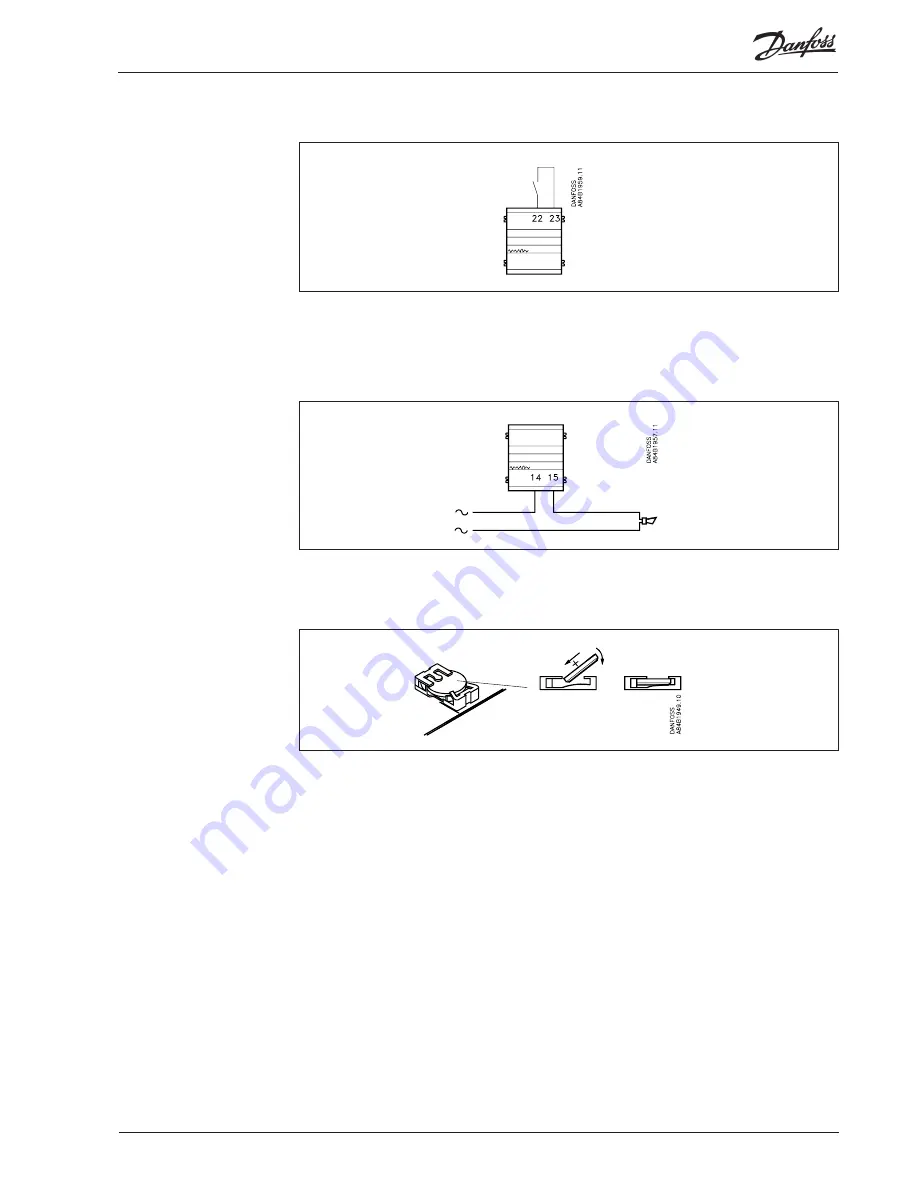
You may change manually between two diff erent alarm routes. The DI2 ON/OFF input can be
connected to a contact function. When the DI2 input is cut in, the alarms will be sent via route 2
(optional des ti nations). (Cf. section “AKA Alarm Table”).
The DO2 output can be used for connecting an alarm function. There is connection between terminals
13 and 14 when the gateway is energised and there is no alarm. This connec tion is interrupted for two
minutes when a status 1 alarm is received from a control ler, or if the supply voltage to the gateway
fails.
Manual change-over of
alarm routing
Alarm relay
Battery
The gateway is provided with battery backup securing the settings and log collections.
When the battery needs to be replaced, an alarm message is sent.
When a battery is replaced, make sure that the supply voltage is not removed from the gateway. If the bat-
tery and supply voltage are both removed at the same time, the clock setup, log setup, collected log data,
master control setups and possibly EKC installation data will all be lost.
3 V
CR2032
AKA
245
Manual RS8DT102 © Danfoss 09/2004
9


