background image

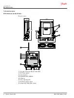
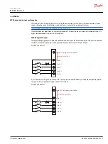
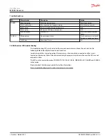
MP08A analog outputs
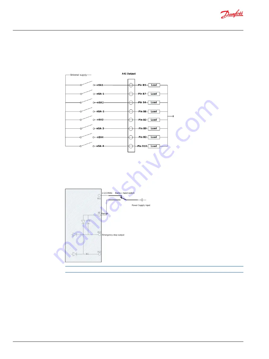
The illustration below shows the pinout information for outputs 1-4. Maximum of 2A per output.
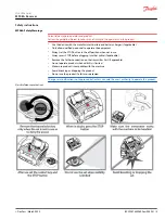
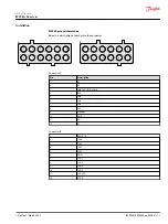
DEUTSCH connector

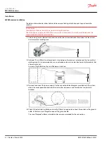
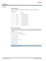
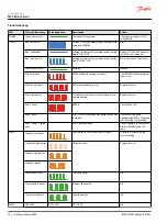
MP08A radio/manual option
The receiver has the possibility to connect to an external switch for changing from Radio mode to Manual

mode if needed. Thus, all inputs and outputs of the receiver will be voided, except from the emergency

stop output.

This option is exclusive to MP08A.

User Manual

MP08A Receiver

Installation


10 | 

©

 Danfoss | March 2022

BC292475492602en-000201

Summary of Contents for MP08A

Page 1: ...User Manual Remote Control MP08A Receiver www danfoss com...

Page 2: ...story Table of revisions Date Changed Rev March 2022 Updated safety information 0201 January 2019 Rebranded to Danfoss Power Solutions 0101 User Manual MP08A Receiver 2 Danfoss March 2022 BC2924754926...

Page 3: ...on Receiver installation 8 Input and output configuration 9 Digital outputs 9 Analog outputs 10 Radio manual option exclusive to MP08A 10 Pinout information 11 Troubleshooting MP08 Receiver Faceplates...

Page 4: ...e brouillage et 2 l utilisateur de l appareil doit accepter tout brouillage radio lectrique subi m me si le brouillage est susceptible d en compromettre le fonctionnement MP08A General Safety The foll...

Page 5: ...use Always press STOP before plugging in tether cable if applicable Remove the Tether connection on the transmitter First if applicable Do not operate product when visibility is limited Make sure prod...

Page 6: ...2 25 118 73 1 Fixing slots fixed assembly or anti vibration 2 DEUTSCH connector 3 External antenna 4 Removable internal EEPROM 5 RF Module 6 External signaling LEDs 7 DEUTSCH connector pinout 8 Analog...

Page 7: ...OFF outputs 4 2A per Output 8 2A per Output Proportional outputs 4 PWM 2 5A per Output 4 Voltage 20mA per Output CAN Bus Protocols N A CANopen ON OFF inputs 4 2 Proportional inputs 1 Response Time 100...

Page 8: ...ed antenna in a clear location only for models that allow an antenna In areas of high vibration the use of dampers is advised 3 Proceed to connect the power supply Use the connection block diagram pro...

Page 9: ...gital output group K1 K4 have a common contact at pin B1 of the connector This pin is connected to pin B12 stop for powering up the group of outputs Maximum of 2A per output DEUTSCH connector K1 K2 K3...

Page 10: ...ual option The receiver has the possibility to connect to an external switch for changing from Radio mode to Manual mode if needed Thus all inputs and outputs of the receiver will be voided except fro...

Page 11: ...A B 8 7 4 3 Connector A Pin Description 1 K2 2 K4 3 IN 0 10V IN 0 20mA 4 N A 5 IN4 6 IN3 7 IN2 8 IN1 9 Manual 10 GND 11 K3 12 K1 Connector B 1 PW K1 4 2 1SA4 3 1SA3 4 1SA2 5 1SA1 6 GND 7 1SA 1 8 1SA...

Page 12: ...s finished HARDOK Green continuous Receiver hardware OK Operate Red pulsing EEPROM error data corruption CAN bus error if CANERR activates Reprogram EEPROM Red other Electronic board hardware breakdow...

Page 13: ...LED troubleshooting The troubleshooting LEDs are located on the receiver board or accessible on the outside Use the following table to identify faults and corrective action In order to reach the inter...

Page 14: ...Replace receiver Red triple pulses Secondary micro error or error between micro communication Replace receiver Red 4 pulses ERROR Check DIAG1 LED Red 5 pulses After 15 sec Not all expansion boards hav...

Page 15: ...Expansion boards Red 4 pulses A Transmitted CAN frame has been lost N A Red 5 pulses A Received CAN Frame has been lost N A Red continuous CAN Bus OFF Verify CAN connections and Status CANRUN Green f...

Page 16: ...anfoss Power Solutions US Company 2800 East 13th Street Ames IA 50010 USA Phone 1 515 239 6000 Danfoss Power Solutions Trading Shanghai Co Ltd Building 22 No 1000 Jin Hai Rd Jin Qiao Pudong New Distri...

Reviews: