background image

Danfoss Power Solutions is a global manufacturer and supplier of high-quality hydraulic and
electric components. We specialize in providing state-of-the-art technology and solutions
that excel in the harsh operating conditions of the mobile off-highway market as well as the
marine sector. Building on our extensive applications expertise, we work closely with you to
ensure exceptional performance for a broad range of applications. We help you and other
customers around the world speed up system development, reduce costs and bring vehicles
and vessels to market faster.

Danfoss Power Solutions – your strongest partner in mobile hydraulics and mobile
electrification.
Go to www.danfoss.com for further product information.

We offer you expert worldwide support for ensuring the best possible solutions for
outstanding performance. And with an extensive network of Global Service Partners, we also
provide you with comprehensive global service for all of our components.

Local address:

Danfoss 

Power Solutions GmbH & Co. OHG

Krokamp 35

D-24539 Neumünster, Germany

Phone: +49 4321 871 0

Danfoss 

Power Solutions ApS

Nordborgvej 81

DK-6430 Nordborg, Denmark

Phone: +45 7488 2222

Danfoss 

Power Solutions (US) Company

2800 East 13th Street

Ames, IA 50010, USA

Phone: +1 515 239 6000

Danfoss 

Power Solutions Trading

(Shanghai) Co., Ltd.

Building #22, No. 1000 Jin Hai Rd

Jin Qiao, Pudong New District

Shanghai, China 201206

Phone: +86 21 2080 6201

Danfoss can accept no responsibility for possible errors in catalogues, brochures and other printed material. Danfoss reserves the right to alter its products without notice. This also applies to products

already on order provided that such alterations can be made without subsequent changes being necessary in specifications already agreed.

All trademarks in this material are property of the respective companies. Danfoss and the Danfoss logotype are trademarks of Danfoss A/S. All rights reserved.

©

 Danfoss | March 2022

BC292475492602en-000201

Products we offer:

Cartridge valves

DCV directional control

valves

Electric converters

Electric machines

Electric motors

Gear motors

Gear pumps

Hydraulic integrated

circuits (HICs)

Hydrostatic motors

Hydrostatic pumps

Orbital motors

PLUS+1

®

 controllers

PLUS+1

®

 displays

PLUS+1

®

 joysticks and

pedals

PLUS+1

®

 operator

interfaces

PLUS+1

®

 sensors

PLUS+1

®

 software

PLUS+1

®

 software services,

support and training

Position controls and

sensors

PVG proportional valves

Steering components and

systems

Telematics

Hydro-Gear

www.hydro-gear.com
Daikin-Sauer-Danfoss

www.daikin-sauer-danfoss.com 

Summary of Contents for MP08A

Page 1: ...User Manual Remote Control MP08A Receiver www danfoss com...

Page 2: ...story Table of revisions Date Changed Rev March 2022 Updated safety information 0201 January 2019 Rebranded to Danfoss Power Solutions 0101 User Manual MP08A Receiver 2 Danfoss March 2022 BC2924754926...

Page 3: ...on Receiver installation 8 Input and output configuration 9 Digital outputs 9 Analog outputs 10 Radio manual option exclusive to MP08A 10 Pinout information 11 Troubleshooting MP08 Receiver Faceplates...

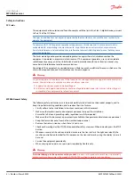
Page 4: ...e brouillage et 2 l utilisateur de l appareil doit accepter tout brouillage radio lectrique subi m me si le brouillage est susceptible d en compromettre le fonctionnement MP08A General Safety The foll...

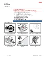
Page 5: ...use Always press STOP before plugging in tether cable if applicable Remove the Tether connection on the transmitter First if applicable Do not operate product when visibility is limited Make sure prod...

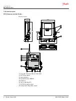
Page 6: ...2 25 118 73 1 Fixing slots fixed assembly or anti vibration 2 DEUTSCH connector 3 External antenna 4 Removable internal EEPROM 5 RF Module 6 External signaling LEDs 7 DEUTSCH connector pinout 8 Analog...

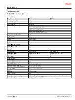
Page 7: ...OFF outputs 4 2A per Output 8 2A per Output Proportional outputs 4 PWM 2 5A per Output 4 Voltage 20mA per Output CAN Bus Protocols N A CANopen ON OFF inputs 4 2 Proportional inputs 1 Response Time 100...

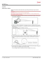
Page 8: ...ed antenna in a clear location only for models that allow an antenna In areas of high vibration the use of dampers is advised 3 Proceed to connect the power supply Use the connection block diagram pro...

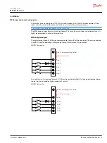
Page 9: ...gital output group K1 K4 have a common contact at pin B1 of the connector This pin is connected to pin B12 stop for powering up the group of outputs Maximum of 2A per output DEUTSCH connector K1 K2 K3...

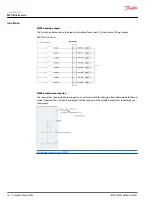
Page 10: ...ual option The receiver has the possibility to connect to an external switch for changing from Radio mode to Manual mode if needed Thus all inputs and outputs of the receiver will be voided except fro...

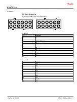
Page 11: ...A B 8 7 4 3 Connector A Pin Description 1 K2 2 K4 3 IN 0 10V IN 0 20mA 4 N A 5 IN4 6 IN3 7 IN2 8 IN1 9 Manual 10 GND 11 K3 12 K1 Connector B 1 PW K1 4 2 1SA4 3 1SA3 4 1SA2 5 1SA1 6 GND 7 1SA 1 8 1SA...

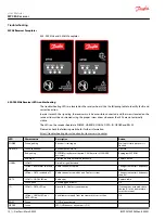
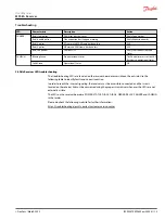
Page 12: ...s finished HARDOK Green continuous Receiver hardware OK Operate Red pulsing EEPROM error data corruption CAN bus error if CANERR activates Reprogram EEPROM Red other Electronic board hardware breakdow...

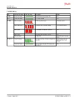
Page 13: ...LED troubleshooting The troubleshooting LEDs are located on the receiver board or accessible on the outside Use the following table to identify faults and corrective action In order to reach the inter...

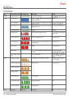
Page 14: ...Replace receiver Red triple pulses Secondary micro error or error between micro communication Replace receiver Red 4 pulses ERROR Check DIAG1 LED Red 5 pulses After 15 sec Not all expansion boards hav...

Page 15: ...Expansion boards Red 4 pulses A Transmitted CAN frame has been lost N A Red 5 pulses A Received CAN Frame has been lost N A Red continuous CAN Bus OFF Verify CAN connections and Status CANRUN Green f...

Page 16: ...anfoss Power Solutions US Company 2800 East 13th Street Ames IA 50010 USA Phone 1 515 239 6000 Danfoss Power Solutions Trading Shanghai Co Ltd Building 22 No 1000 Jin Hai Rd Jin Qiao Pudong New Distri...

Reviews: