
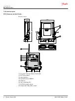
MP08A receiver installation
The below information describes hazards to be aware of during installation and steps to locate the
receiver.
Risk of shock
Completely shut down the machine when installing the receiver.
Check the power supply and shut off the main switch to disconnect the interface cable between the
receiver and the machine's electrical box.
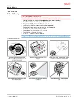
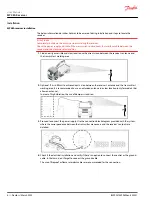
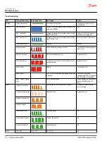
1. Find an easily accessible and clear location with a direct vision between the receiver's antenna and
the transmitter's working area.
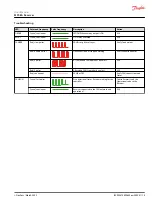
2. Optional: If it is difficult to achieve direct vision between the receiver's antenna and the transmitter's
working area, it is recommended to use an extended antenna in a clear location (only for models that
allow an antenna).
In areas of high vibration, the use of dampers is advised.
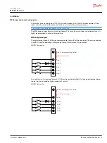
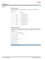
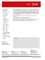
3. Proceed to connect the power supply. Use the connection block diagram provided with the system,
where the correspondence between the transmitter maneuvers and the receiver's outputs are
detailed.
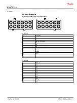
7
IN2
8
IN1
9
MANUAL
10
GND
11
K3
12
K1
6
IN3
5
IN4
4
3
IN 0-10V
2
K4
1
K2
IN 0-20mA
1
PW
2
1SA4
3
1SA3
4
1SA2
5
1SA1
6
GND
12
STOP
11
+12/24V
10
9
8
7
K1-4
1SA-
4
1SA-3
1SA-
2
1SA-1
A
B
4. Check if the electrical installation and verify if there's an option to connect the neutral or the ground
cable. In that case, don't forget to connect the ground cable.
The use of fireproof or flame retardant cables are recommended for the connection.
User Manual
MP08A Receiver
Installation
8 |
©
Danfoss | March 2022
BC292475492602en-000201


