2.4GHz Receiver LED troubleshooting
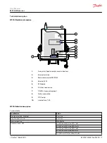
The troubleshooting LEDs are located on the receiver board or accessible on the outside. Use the
following table to identify faults and corrective action.
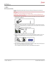
In order to reach the internal signaling, the receiver must be accessible, connected and the screws
located on the receiver lid must be unscrewed using the proper screw driver whenever the LEDs are not
externally visible.
The LEDs on the receiver board are POWER, STATUS, DIAG1, DIAG2, ORDER, RELAY, CANERR and CANRUN
in that order.
Please do check the following website for further information:
https://troubleshooting.dps-rct.com/en/customer-service-center
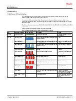
LED
Color and frequency
Pulse frequency
Description
Action
POWER
Green | continuous
Switched ON if powered
Check power supply if LED is
switched off.
STATUS
Blue | fast pulses
System is starting; establishing connection with
radio and EEPROM
Wait
Blue | continuous
Waiting for transmitter communication, coming
from ACTIVE STOP
Release STOP button and press
START on the transmitter.
Blue | slow pulses
Waiting for transmitter communication, coming
from PASSIVE STOP
Press Start on the Transmitter
Green | continuous
Working
Operate
Red | slow pulses
EEPROM module missing or corrupt
Check EEPROM and reprogram
if necessary
Red | double pulses
Radio communication error
Replace receiver
Red | triple pulses
Secondary micro error or error between micro
communication
Replace receiver
Red | 4 pulses
ERROR
Check DIAG1 LED
Red | 5 pulses
After 15 sec Not all expansion boards have been
initialized
Check CAN wiring and
Configuration(EEP or Expansion
ID#), Check Bus Termination.
Red | 1 Long + 1 short
pulse
CAN Signature ERROR
Check Signature in Compliance
Block and EEPROM are the
same.
User Manual
MPCAN Receiver
Troubleshooting
©
Danfoss | March 2022
BC292573933619en-000201 | 13


