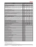
14
User
Guide RS8GD602 © Danfoss 2015-10
Optyma
Plus
TM
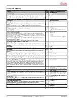
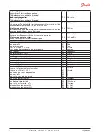
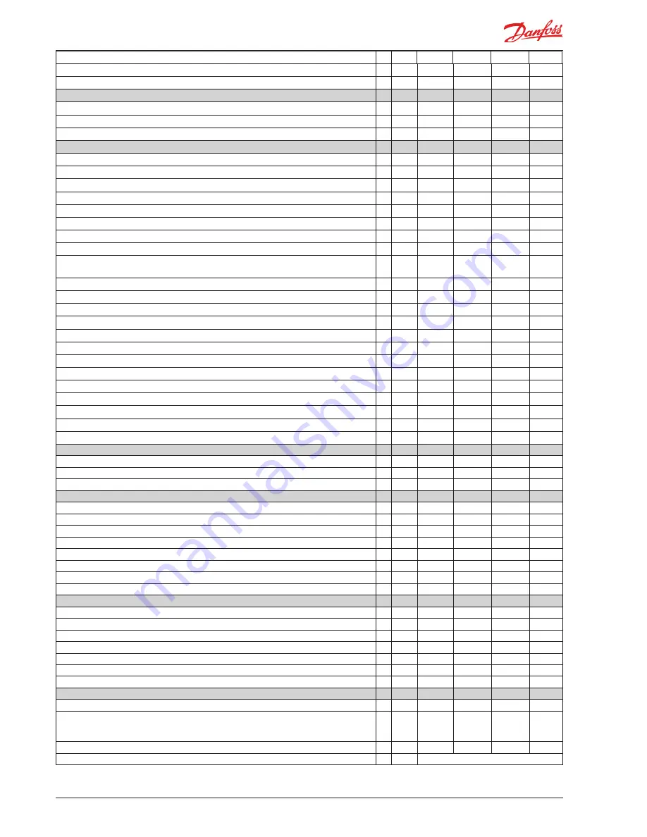
Max. condensing temperature (highest permitted Tc reference)
r83
0°C
50°C
40°C
Max. discharge gas temperature Td
r84
50°C
160°C
135°C
Alarms
Alarm time delay on signal on the DI2 input
A28
0 min.
240 min.
30 min.
Alarm for insufficient cooling in condenser. Set temperature difference.
A70
3.0 K
20.0 K
10.0 K
Delay time for A70 alarm
A71
5 min.
240 min.
30 min.
Compressor
Min. ON-time
c01
5 s
240 s
5 s
Min. OFF-time
c02
3 s
240 s
30 s
Min. time between compressor starts
c07
0 min.
30 min.
5 min.
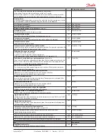
Pump down limit at which the compressor is stopped (setting 0.0 = no function)
C33
0,0 bar
15,0 bar
0,0 bar
Min. compressor speed
c46
25 Hz
70 Hz
30 Hz
Start speed for compressor
c47
30 Hz
70 Hz
50 Hz
Max. compressor speed
c48
50 Hz
100 Hz
100 Hz
Max. compressor speed during night operation (%-value of c48)
c69
50%
100%
70%
Definition of compressor control: 0=no external start/stop; 1=switch on DI1 must start/stop
; 2=inverter compressor speed control
c71
0
2
1
Time delay for high Td. The compressor will stop when time expires.
c72
0 min.
20 min.
3 min.
Max. pressure. Compressor stops if a higher pressure is recorded
c73
7.0 bar
50.0 bar
23.0 bar
Difference for max. pressure (c73)
c74
1.0 bar
10.0 bar
3.0 bar
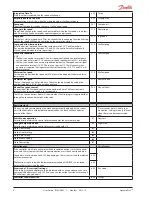
Min. suction pressure Ps. Compressor stops if a lower pressure is recorded
c75
-0.3 bar
10.0 bar
3.0 bar
Difference for min. suction pressure and pump down
c76
0.1 bar
5.0 bar
0.7 bar
Amplification factor Kp for compressors PI-regulation
c82
3,0
30,0
20,0
Integration time Tn for compressors PI-regulation
c83
30 s
360 s
60 s
Liquid Injection Offset
c88
0.1 K
20.0 K
5.0 K
Liquid Injection hysterese
c89
10.0 K
30.0 K
15.0 K
Compressor stop delay after Liquid injection
c90
0 s
10 s
3 s
Desired compressor speed if the signal from the pressure transmitter Ps fails
c93
25 Hz
70 Hz
60 Hz
Min On time during Low Ambient LP
c94
0
0
120
Measured Tc for which the Comp min speed is raised to StartSpeed
c95
40,0
10,0
70,0
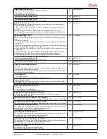
Control parameters
Amplification factor Kp for PI-regulation
n04
1.0
20.0
7.0
Integration time Tn for PI-regulation
n05
20
120
40
Kp max for PI regulation when the measurement is far from reference
n95
5,0
50,0
20,0
Fan
Readout of fan speed in %
F07
-
-
-
Permitted change in fan speed (to a lower value) % per second.
F14
1,0%
5,0%
1,0%
Jog speed (speed as a % when the fan is started)
F15
10%
100%
40%
Jog speed at low temperature
F16
0%
40%
10%
Definition of fan control: 0=Off; 1=Internal control. 2=External speed control
F17
0
2
1
Minimum fan speed. Decreased need will stop the fan.
F18
0%
40%
10%
Maximum fan speed
F19
40%
100%
100%
Manual control of the fan's speed. (Only when r12 is set to -1)
F20
0%
100%
0%
Real time clock
Time at which they switch to day operation
t17
0 hrs
23 hrs
0
Time at which they switch to night operation
t18
0 hrs
23 hrs
0
Clock - Setting of hours
t07
0 hrs
23 hrs
0
Clock - Setting of minute
t08
0 min.
59 min.
0
Clock - Setting of date
t45
1 day
31 day
1
Clock - Setting of month
t46
1 mon.
12 mon.
1
Clock - Setting of year
t47
0 year
99 year
0
Miscellaneous
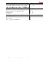
Network address
o03
0
240
0
On/Off switch (Service Pin message)
IMPORTANT! o61
must
be set prior to o04
(used at LON 485 only)
o04
0/Off
1/On
0/Off
Access code (access to all settings)
o05
0
100
0
Readout of controllers software version
o08
continued
Code
Min.
Max.
Fac.
Actual


