background image

180R9288_AQ109686503100en-001301 | 57

© Danfoss | 2023.12

Operation guide 

Installation, Operation and Maintenance Manual for PAHT 20-90 pumps

3

Motor
Manual

connections must be checked and tightened if necessary.
Bearing size and type are specified on the rating plate. Motor 
types HMA3 and HMC3 is as standard with lifetime greased 
bearings in motors size 

180 for cast iron and size 

132 for 

aluminium. Motor types HMA2 and HMC2 is as standard 
with lifetime greased bearing in motors size 

225.

Motor types MS and Y2E is as standard with lifetime greased 
bearing in motors size 

160.

Typical duty hours for lifetime lubricated bearings.

Frame size

Poles

Typical lifetime

56 - 160

2 - 8

40,000h

180

2

35,000h

200

2

27,000h

225

2

23,000h

180 - 225

4 - 8

40,000h

Motors with a re-greasing system must be lubricated with 
high quality lithium complex grease, NLGI grade 2 or 3, with 
a temperature range of between -40°C to +150°C.
Motors are normal fitted with a data plate with greasing 
information; if it is missing use the following re-greasing 
intervals.

Frame 

size

Grease  

(g)

2 pole

(h)

4 pole

(h)

6 pole  

(h)

8 pole  

(h)

160

20

4200

7000

8500

8500

180

20

4200

7000

8500

8500

200

25

3100

6500

8500

8500

225

25

3100

6500

8500

8500

250

35

2000

6000

7000

7000

280

35

2000

6000

7000

7000

315

50

1500

5500

6500

6500

355

60

1000

4000

5000

6000

400

80

800

3000

4000

6000

Grease the motor while running, open the grease outlet plug 
and let the motor run 1-2 hours before the outlet grease plug 
is closed again.
Grease the motor for the first time during commissioning. 

The following applies in general for both lifetime lubricated 
and re-lubricated bearings:
At 60Hz the time will be reduced by app. 20%.
Data for vertically mounted motors are half of the above 
values.

The table values are based on an ambient temperature of 
25°C. The values must be halved for every 15K increase in 
bearing temperature.
Higher speed operations, e.g. frequency converter drive will 
require shorter greasing intervals. Typically, doubling the 
speed will reduce the values by 50%. 

Special note for Atex Zone 22 and nA motors

Designation of motor according to IEC standard:
II 3D Ex tc IIIB T120°C
II 3G Ex nA IIC T3

The hazardous 3-phase asynchronous motors are in 
accordance with International standard IEC 60079-31 and 
IEC 60079-15.
Only one electrical installation may be installed in one 
specified area (zone).

Only certificated cable glands may be used. Unused glands 
must be closed.
Connections must be made in such a way as to ensure that 
a permanently safe electrical connection is maintained, both 
for the main supply and earth connection.
Installations must be in accordance with actual standards 
for installation in hazardours area.

It is recommended that the IEC standard is followed according 
to temperature and dust on the motor surface.
The use of motors with so much surface dust that the motor 
temperature increases is not permitted.
Regularly cleaning is recommended. 
The radial shaft sealing ring is part of the ATEX certification. 
It is important that the ring is always intact.
The shaft sealing must be regularly checked, and if dry it 
must be lubricated. It is recommended that the seal is re-
lubricated regularly.
Always use the original seal ring when replaced.
Replacing bearings also means replacing the seals.

All machines must be inspected regularly for mechanical 
damage.
The user is responsible for changing parts in accordance 
with the lifetime of parts, in particular:
bearings, grease and lubrication of shaft sealing.

Maintenance, repairs and replacement on this type must 
only be carried out by qualified specialists.

Summary of Contents for PAHT

Page 1: ...Danfoss 2023 12 180R9288_AQ109686503100en 001301 1 Operation guide PAHT pumps PAHT 20 25 32 and PAHT 50 63 70 80 90 Operation Installation and Maintenance Manual hpp danfoss com...

Page 2: ...ion transportation handling lifting and storage 8 4 1 Arrival inspection 8 4 2 Warning 8 4 3 General safety information 8 4 4 Transport and handling 8 4 5 Return to supplier 9 4 6 Storage 9 5 Installa...

Page 3: ...ck into operation 14 7 8 Storage of the pump 14 8 Troubleshooting and scrapping criteria 15 8 1 General safety information 15 8 2 Operational conditions which can cause pump failures 15 8 3 Mechanical...

Page 4: ...no XXXXXX04 XXX PAHT 63 Code no 180B0086 Serial no XXXXXX04 XXX PAHT 70 Code no 180B0087 Serial no XXXXXX04 XXX PAHT 80 Code no 180B0088 Serial no XXXXXX04 XXX PAHT 90 Code no 180B0089 Serial no XXXX...

Page 5: ...talled and used in accordance with existing national local sanitary safety regulations and laws It is the responsibility of the safety officer or the chief operator to assure compliance with all local...

Page 6: ...a Danger Hot sign When using an electric motor the motor must always be supplied with adequate cooling ventilation When using an electric motor together with a VFD Variable Frequency Drive the motor m...

Page 7: ...ed to have sufficient space available around the pump in order to ensure easy access Sufficient space means at least 1 meter 40 inches around the pump When working with high pressures it is important...

Page 8: ...hat can result in damage to piping equipment and internal parts of the pump 4 Arrival inspection transportation handling lifting and storage 4 1 Arrival inspection The pump is packed in a cardboard or...

Page 9: ...in personal injury and or damage to the pump unit see appendix 2 Instruction Once the lifting is done the lifting eye must be removed from the pump 4 5 Return to supplier Please see maintenance chapte...

Page 10: ...irt or rust is not removed the pump and the valves can be damaged In worst case the pump can be damaged beyond repair 5 3 Fluid temperature Before start up the fluid and pump housing temperature must...

Page 11: ...1 Bar or more precise CP11 Check coupling distance air gab movement of the spider 3 5 mm CP12 Check correct connections on the pump in outlet CP13 Check piping for possible air gaps 5 7 Lifting and po...

Page 12: ...to close all bleeding and draining plugs Adjust pressure relief valve to minimum setting Check rotation of the high pressure pump by description in 5 15 Start high pressure pump for 2 minutes to make...

Page 13: ...shooting If the pump is not stopped for inspection as recommended it can lead to damage of the pump or break down See also service and warranty section in appendix 1 Data sheet and appendix 2 Instruct...

Page 14: ...sembling and Assembling Instruction available at www danfoss high pressurepumps com Clean all the parts and surfaces with a fluid compatible with the materials found in the pump Wipe the parts clean a...

Page 15: ...falling If water is dripping into the electric motor it can cause electric shock fire short of circuit or even death When mounting the pump vertically always mount the motor above the pump to avoid wa...

Page 16: ...16 180R9288_AQ109686503100en 001301 Danfoss 2023 12 Operation guide Installation Operation and Maintenance Manual for PAHT 20 90 pumps...

Page 17: ...503100en 001301 17 Danfoss 2023 12 Operation guide Installation Operation and Maintenance Manual for PAHT 20 90 pumps Operation guide Appendices PAHT 20 90 Installation Operation and Maintenance Manua...

Page 18: ...a sheet PAHT 2 308 pumps AI106586503085en 000901 19 2 Pump instruction PAHT 20 32 and PAHT 50 90 AN101386502958en 000603 43 3 Electric motor manual 180R9230 55 4 Parts list PAHT AX322445815902en 00020...

Page 19: ...Danfoss 2023 12 180R9288_AQ109686503100en 001301 1 Data sheet PAHT pumps PAHT 2 6 3 PAHT 10 12 5 PAHT 20 25 PAHT 50 90 and PAHT 256 308 hpp danfoss com...

Page 20: ...pressure 31 6 Motor requirements 32 7 Installation 33 7 1 Filtration 33 7 2 Noise 33 7 3 Open system design 34 7 4 Closed system design 35 8 Dimensions and connections 36 8 1 PAHT 2 6 3 36 8 2 PAHT 10...

Page 21: ...mption of any comparable pump on the market Easy installation The lightest and most compact design available Pump can be installed horizontally or vertically No pulsation dampeners necessary due to ex...

Page 22: ...000 1000 1000 Max speed rpm 3000 3000 3000 3000 2400 2400 Typical flow Flow curves available in section 5 1000 rpm at max pressure l min 0 7 2 0 3 0 5 5 7 6 10 2 1500 rpm at max pressure l min 1 7 3 6...

Page 23: ...x speed rpm 2400 2400 2400 2400 2400 2400 Typical flow Flow curves available in section 5 1000 rpm at max pressure l min 16 9 17 9 20 6 23 28 0 31 5 1500 rpm at max pressure l min 27 0 27 5 33 2 35 3...

Page 24: ...00 1000 1000 Max speed rpm 1800 1800 1800 1800 1800 Typical flow Flow curves available in section 5 1000 rpm at max pressure l min 43 7 50 5 57 7 68 3 77 6 1500 rpm at max pressure l min 68 7 82 1 92...

Page 25: ...700 Max speed rpm 1250 1250 Typical flow Flow curves available in section 5 450 rpm at max pressure l min 89 6 107 8 1250 rpm at max pressure l min 294 4 354 2 450 rpm at max pressure gpm 23 3 28 0 1...

Page 26: ...flow equals the theoretical flow Q th Q th Theoretical flow l min gpm Q pmax Flows at max pressure l min and gpm see 4 1 4 4 p max Max pressure barg psig p Pressure barg psig V Displacement cm3 rev n...

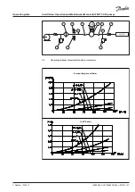
Page 27: ...ce Manual for PAHT 20 90 pumps 5 2 PAHT 10 12 5 typical flow curves at max pressure 30 25 20 15 10 5 rpm PAHT 10 0 PAHT 12 5 l min 1 0 0 0 1 2 0 0 1 4 0 0 1 6 5 0 1 8 0 0 2 2 0 0 2 0 0 0 2 4 0 0 PAHT...

Page 28: ...Manual for PAHT 20 90 pumps 5 3 PAHT 20 32 typical flow curves at max pressure 80 70 60 50 40 30 20 10 0 rpm PAHT 20 PAHT 25 PAHT 32 l min 7 0 0 9 5 0 1 2 0 0 1 4 5 0 1 9 5 0 1 7 0 0 2 2 0 0 2 4 0 0 P...

Page 29: ...Manual for PAHT 20 90 pumps 5 4 PAHT 20 32 LP typical flow curves at max pressure 80 70 60 50 40 30 20 10 0 700 950 1200 1450 1950 1700 2200 rpm l min 2400 0 0 5 0 10 0 15 0 20 0 25 0 700 950 1200 145...

Page 30: ...or PAHT 20 90 pumps 5 5 PAHT 50 90 typical flow curves at max pressure 160 140 120 100 80 60 40 20 0 l min 1 2 0 0 9 5 0 1 4 5 0 1 7 0 0 1 8 0 0 7 0 0 rpm PAHT 80 PAHT 50 PAHT 63 PAHT 70 PAHT 90 0 5 1...

Page 31: ...for PAHT 20 90 pumps 5 6 PAHT 256 308 typical flow curves at max pressure 400 350 300 250 200 150 100 50 0 l min 5 5 0 6 5 0 7 5 0 8 5 0 1 0 5 0 1 1 5 0 1 2 5 0 9 5 0 4 5 0 rpm PAHT 256 PAHT 308 30 20...

Page 32: ...item 5 you can deter mine the rpm of the pump at the desired flow The required torque is calculated as follows V x p M 62 8 x To determine the correct motor size both the power and torque requirement...

Page 33: ...ges which typically have only 50 filtration efficiency This means that out of 100 000 particles that enter such filters 50 000 particles pass right through them compare this to precision depth filters...

Page 34: ...erature switch Install the monitoring temperature switch 4 between the filter and the pump on either side of the monitoring pressure switch Set the temperature value according to technical data item 4...

Page 35: ...the temperature value according to technical data item 4 The monitoring temperature stops the pump if inlet temperature is higher than the set value E Hoses Always use flexible hoses 6 to minimize vi...

Page 36: ...36 180R9288_AQ109686503100en 001301 Danfoss 2023 12 Operation guide Installation Operation and Maintenance Manual for PAHT 20 90 pumps 8 Dimensions and connections 8 1 PAHT 2 6 3...

Page 37: ...180R9288_AQ109686503100en 001301 37 Danfoss 2023 12 Operation guide Installation Operation and Maintenance Manual for PAHT 20 90 pumps 8 2 PAHT 10 12 5...

Page 38: ...38 180R9288_AQ109686503100en 001301 Danfoss 2023 12 Operation guide Installation Operation and Maintenance Manual for PAHT 20 90 pumps 8 3 PAHT 20 32...

Page 39: ...180R9288_AQ109686503100en 001301 39 Danfoss 2023 12 Operation guide Installation Operation and Maintenance Manual for PAHT 20 90 pumps 8 4 PAHT 50 90...

Page 40: ...40 180R9288_AQ109686503100en 001301 Danfoss 2023 12 Operation guide Installation Operation and Maintenance Manual for PAHT 20 90 pumps 8 5 PAHT 256 308...

Page 41: ...a pump may be greatly shortened if Danfoss recommendations concerning system design and operation are not followed In our experience poor filtration is the number one cause of pump damage Other factor...

Page 42: ...Danfoss DCS SGDPT SI 2023 12 42 180R9288_AQ109686503100en 001301 Operation guide Installation Operation and Maintenance Manual for PAHT 20 90 pumps AI106586503085en 001001...

Page 43: ...Danfoss 2023 12 180R9288_AQ109686503100en 001301 1 Instruction PAHT pump PAHT 20 32 and PAHT 50 90 hpp danfoss com...

Page 44: ...comments 48 3 Building up the pump unit 48 3 1 Mounting 48 3 2 Direction of rotation 49 3 3 Orientation 49 3 4 Protection from too high system pressures 49 3 5 Connections 50 3 5 1 PAHT 20 32 50 3 5 2...

Page 45: ...ions and fittings with small pressure losses B Inlet filter Install the inlet filter 1 in front of the tank 2 Place the tank above pump and pump inlet Please consult the Danfoss filter data sheet for...

Page 46: ...sure switch Install the monitoring pressure switch 3 between the filter and the pump inlet Set the minimum inlet pressure according to specifications described in item 4 technical data The monitoring...

Page 47: ...47 Danfoss 2023 12 Operation guide Installation Operation and Maintenance Manual for PAHT 20 90 pumps 2 6 General guidelines for calculation of pressure losses M 2 SYSTEM 1 4 5 5 6 7 3 PI PI 8 In smo...

Page 48: ...ly the return line and inlet to the pump should be placed in opposite ends of the tank to calm and deaerate the water and to ensure optimum opportunity for particles to settle Pump suction line should...

Page 49: ...tal position and it can be mounted orientated in the vertical position with the shaft upwards The pump cannot be vertically mounted orientated with the shaft facing downwards 3 4 Protection from too h...

Page 50: ...ontaining a rubber sealing element 3 5 2PAHT 50 90 I Inlet O Outlet C Bleeding XI Gauge port inlet XO Gauge port oulet PAHT 50 63 70 80 90 10 8 45 2 DIN 6885 There are two 1 4 ports on the inlet side...

Page 51: ...t C To protect the pump from too high fluid temperature a temperature switch of 50 C 122 F should be mounted on the inlet side If the whole pump flow is bypassed over the relief valve then the fluid t...

Page 52: ...nt flush the pump with an anti freeze medium type monopropylene glycol to prevent internal corrosion or frost in the pump If DI water with conductivity level below 20 S cm is used you can drain the pu...

Page 53: ...flow according to measurements made in the past We advise that the above mentioned parameter during the extended service interval is inspected for every 500 2 000 hours beyond the 8 000 hours The pump...

Page 54: ...Danfoss DCS SGDPT SI 2023 12 54 180R9288_AQ109686503100en 001301 Operation guide Installation Operation and Maintenance Manual for PAHT 20 90 pumps 180R9283_AN101386502958en 000603...

Page 55: ...180R9288_AQ109686503100en 001301 55 Danfoss 2023 12 Operation guide Installation Operation and Maintenance Manual for PAHT 20 90 pumps M a n u a l Electric Motors Motor Manual hoyermotors com...

Page 56: ...cuit forces It is important to ensure that the mounting conditions do not cause resonance with the rotational frequency and the doubled supply frequency Only mount or remove drive components pulley co...

Page 57: ...mounted motors are half of the above values The table values are based on an ambient temperature of 25 C The values must be halved for every 15K increase in bearing temperature Higher speed operation...

Page 58: ...anfoss 2023 12 Operation guide Installation Operation and Maintenance Manual for PAHT 20 90 pumps Connection diagram Anschlu diagram Anslutningdiagramm Forbindelsesdiagram Aansluitdiagram Connection C...

Page 59: ...180R9288_AQ109686503100en 001301 59 Danfoss 2023 12 Operation guide Installation Operation and Maintenance Manual for PAHT 20 90 pumps...

Page 60: ...yermotors cn Branch Offices Germany Landsberger Stra e 155 80687 M nchen T 49 89 700 88 235 F 49 89 543 56 333 germany hoyermotors com hoyermotors com Sweden Liljeholmsstranden 5 PO box 44017 SE 100 7...

Page 61: ...Danfoss 2023 12 180R9288_AQ109686503100en 001301 1 Parts list PAHT pumps PAHT 2 6 3 PAHT 10 12 5 PAHT 20 32 PAHT 50 90 and PAHT 256 308 hpp danfoss com...

Page 62: ...General 62 8 Spare parts list for PAHT 20 32 63 9 Exploded view for PAHT 20 32 64 10 Spare parts list for PAHT 50 90 65 11 Exploded view for PAHT 50 90 66 1 General This parts list provides an overvie...

Page 63: ...304 x 5 10 Screw M8 x 16 AISI 304 x 9 1 O ring 102 x 3 NBR x 11 1 End cover CW AISI 316 31 1 Swash plate AISI 431 x x x 32 1 Screw 8 x 16 AISI 304 x x x 34 2 Pin 4 x 14 AISI 304 x x x 61 1 Cylinder ba...

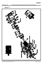
Page 64: ...64 180R9288_AQ109686503100en 001301 Danfoss 2023 12 Operation guide Installation Operation and Maintenance Manual for PAHT 20 90 pumps 9 Exploded view for PAHT 20 32...

Page 65: ...plate AISI 431 x x x x x 32 1 Screw M8 x 20 AISI 304 x x x x x 34 2 Pin 4 x 14 AISI 304 x x x x x 61 1 Cylinder barrel AISI 431 x 62 1 Spring 1 4462 x 64 1 Retainer ball AISI 431 x 65 1 Retainer plat...

Page 66: ...66 180R9288_AQ109686503100en 001301 Danfoss 2023 12 Operation guide Installation Operation and Maintenance Manual for PAHT 20 90 pumps 11 Exploded view for PAHT 50 90...

Page 67: ...180R9288_AQ109686503100en 001301 67 Danfoss 2023 12 Operation guide Installation Operation and Maintenance Manual for PAHT 20 90 pumps...

Page 68: ...Danfoss DCS SGDPT SI 2023 12 68 180R9288_AQ109686503100en 001301 Operation guide Installation Operation and Maintenance Manual for PAHT 20 90 pumps AX322445815902en 000202...

Page 69: ...Danfoss 2023 12 180R9288_AQ109686503100en 001301 1 Guide line PAH PAHT PAHT C PAHT G PAHT 674 PAH F pumps Trouble shooting guide hpp danfoss com...

Page 70: ...PAHT 20 90 pumps Table of Contents Table of Contents Trouble shooting fish bone chart 71 1 No flow no pressure 72 2 Reduced flow reduced pressure 73 3 High torque on electric motor 74 4 Noise from pu...

Page 71: ...eatment 2 1 6 Main filtration 2 1 Wear in pump internal leakage 2 1 7 Type of fluid 2 1 8 High fluid temperature 4 1 Air in fluid 4 2 Bleeding conditions of pump 4 3 Min max nominal inlet pressure 4 4...

Page 72: ...ump is started 1 3 6 Check that the monitor switches are working correctly 1 3 7 Disconnect pump from electric motor and check that the motor is capable of running with no load If motor type relay or...

Page 73: ...s missing the piston is very worn The filters can be bypassed even if they are correctly mounted Some filters can create channelling where particles can pass through the filter in tunnels String wound...

Page 74: ...zed 3 2 2 Check internal parts see item 2 1 3 2 3 Systems with more than one electric motor installed Start motors simultaneously Pumps run in parallel with cascade start may switch off the motor rela...

Page 75: ...nything is broken or worn See 1 No flow item 1 2 Pump reversing WARNING The pump must not run without water for more than a few seconds If the pump takes in water from the high pressure outlet line it...

Page 76: ...ipes or too many bends may create too fast flow turbulence through the pipes and thus increase the noise level 5 3 Hose stiffness 5 3 1 Use a more flexible hose Too stiff hoses cannot dampen the small...

Page 77: ...rn valve plate has scratches and or a polished surface Even small scratches will give a loss of flow Picture 3 A good way to identify a worn valve plate is to hold a straight knife edge over the valve...

Page 78: ...low To check See item 6 1 picture 3 6 2 Port plate 6 3 Swash plate Picture 1 If the swash plate is polished 360 it is an indication of insufficient filtration The surface of the swash plate must be pl...

Page 79: ...180R9288_AQ109686503100en 001301 79 Danfoss 2023 12 Operation guide Installation Operation and Maintenance Manual for PAHT 20 90 pumps...

Page 80: ...Danfoss DCS SGDPT SI 2023 12 80 180R9288_AQ109686503100en 001301 Operation guide Installation Operation and Maintenance Manual for PAHT 20 90 pumps...

Page 81: ...Danfoss 2023 12 180R9288_AQ109686503100en 001301 1 Service guide Right and wrong Trouble shooting guide for water hydraulic systems hpp danfoss com...

Page 82: ...n the return line immediately before the tank Placing the return filter upstream of the final load may damage the pump Pump location 4 Pump always to be placed below water surface level Pump location...

Page 83: ...in joints may cause damage Grease 10 Correctly limited quantities of grease prevent seizing Too much grease may develop biofilm causing operational failures Water supply 13 Fill system with water bef...

Page 84: ...turn filter and bleed the pump Power Packs PPH 4 6 3 10 and 12 5 are self bleeding 2 Start and bleed the system without pressure by opening the bypass valve 3 Add the cleaning agent to give 3 agent wa...

Page 85: ...or provide better cooling Is the control light for low pump suction pressure on The filter is clogging Is the power supply ok Are control lights on Is the filter clogged Is the filter control light o...

Page 86: ...water in the tank very hot Ie above 50 o Is the power supply ok Are control lights on Is the filter clogged Is the filter control light on Replace filter element Contact serviceman Stamp Fill water i...

Page 87: ...180R9288_AQ109686503100en 001301 87 Danfoss 2023 12 Operation guide Installation Operation and Maintenance Manual for PAHT 20 90 pumps...

Page 88: ...Danfoss DCS SGDPT SI 2023 12 88 180R9288_AQ109686503100en 001301 Operation guide Installation Operation and Maintenance Manual for PAHT 20 90 pumps...

Reviews: